Turbidity Sensor
3th November 2019
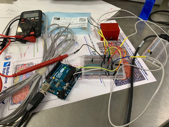
As we got the parts of the turbidity sensor this Friday, The preliminary version of the turbidity sensor has already designed and tested. Luke was beside me all the time and gave me a lot of help.
The whole process of the design is followed by the paper you sent to me. Now the turbidity sensor is connecting to the Arduino and we can get the signal.

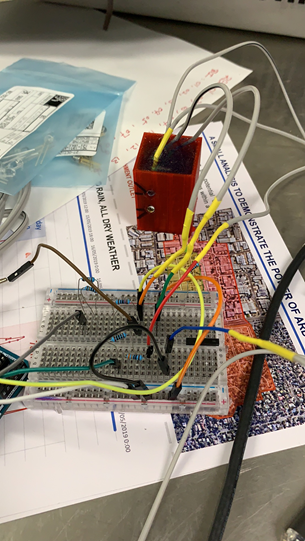
Currently, holes on the box are drilled by hand, next step, the new box with holes will be printed by the 3D printer which will be more accurate in angle. Also, I have asked Luke to order some fixed turbidity solution for further testing and calibration.
5th November 2019 The box of the turbidity is printed by 3D printer.
Luke and I have made some solution with specific NTU at EPHM lab. We got the following results:
1. The reading number(indicating the voltage of the resistor in phototransistor circuit) is 0 when we put the sensor in 1000NTU solution.
2. The reading number is about 0.04 for 100NTU solution.
3. The reading number is about 0.05 for 50NTU solution.
We guess there are several reasons causing the number pretty small: 1. The voltage of the LED and phototransistor does not make them work in full capacity condition. So some resistors are changed and the condition does not change too much. As we do not have enough resistor in our lab, we will buy one and test again after replacement. 2. The distance between the LED and phototransistor is too large, and that causes the phototransistor cannot get enough light. Now I am printing another box which makes the two holes closer, and I will test the new one again tomorrow.
I will let you know if we find the problem.
