BoSL Board v0.3
BOSL BOARD - THE ULTRA LOW POWERED IOT LOGGING DEVICE
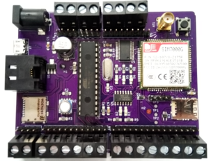
This little beauty costs less than an Arduino and Sim5320a put together, yet it comes already assembled, runs on 4v, is ultra low power consuming (we removed all the overheads of the off the shelf arduinos) and can send data via the CAT-M1 or NB-IoT networks! We estimate that these things can log each minute for over 12months!
Contents
Specifications
Physical Specifications:
Board Width: 88 mm
Board Length: 68.5 mm
Board Height: 18 mm
Weight:
Electrical Specifications:
Max Input Voltage: 5.5 V
Typical Sleep Current: -- μA
Supply Current Surge Requirement: -- mA
Physical Layout
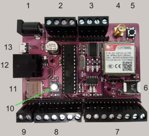
Reference Table: BoSL Board Front
| 1 | DC Power Jack |
| 2 | I2C IO |
| 3 | Power IO |
| 4 | Antenna Connector |
| 5 | Reset Button |
| 6 | SIM Card Holder |
| 7 | Digital IO |
| 8 | Analog IO |
| 9 | Analog IO\TTL Header |
| 10 | Integrated Pressure\Temperature Sensor |
| 11 | SD Card Holder |
| 12 | 8P8P Modular Connector |
| 13 | Micro USB Port |
BoSL BOARD V0.3 PIN LAYOUT
| ATmega328P Pin Number | Arduino IDE pin | Internal Use | Application Notes |
|---|---|---|---|
| 1 | Reset | RST | Pull Low to reset Arduino |
| 2 | D0 | USB RX | Free for use when no micro-USB connected |
| 3 | D1 | USB TX | Free for use when no micro-USB connected |
| 4 | D2 | SIM7000 RX | Not Available for use |
| 5 | D3 | SIM7000 TX | Not Available for use |
| 6 | D4 | SIM7000 On/Off | Not Available for use |
| 7 | VCC | VCC | N/A |
| 8 | GND | GND | N/A |
| 9 | Crystal | XTAL | Not Available for use |
| 10 | Crystal | XTAL | Not Available for use |
| 11 | D5 | SIM7000 DTR | Not Available for use |
| 12 | D6 | None | Free for use |
| 13 | D7 | None | Free for use |
| 14 | D8 | None | Free for use |
| 15 | D9 | None | Free for use |
| 16 | D10 | SD Chip Select | Free for use with no SD card inserted |
| 17 | D11 | SD MOSI | Free for use with no SD card inserted |
| 18 | D12 | SD MISO | Free for use with no SD card inserted |
| 19 | D13 | SD Serial Clock | Free for use with no SD card inserted |
| 20 | VCC | VCC | N/A |
| 21 | Aref | None | Free for use |
| 22 | GND | GND | N/A |
| 23 | A0 | None | Free for use |
| 24 | A1 | None | Free for use |
| 25 | A2 | None | Free for use |
| 26 | A3 | None | Free for use |
| 27 | A4 | SDA | Free for use when not operating I2C bus |
| 28 | A5 | SCL | Free for use when not operating I2C bus |
Low Power Sleep Guide
New Battery Test
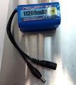
New batteries were set up on 5 on five BoSL boards as an endurance test to see how long each would last. The graphs of various results are displayed below. The linearity in the loggins time graph suggests that the Arduino is logging at regular and consistent intervals (in this test about 577 times per day). The battery's voltage is linear down to about 3300 mV, and then declines sharply before cutting out. The majority of the battery's capacity is thus above the 3300 mV threshold required for in-spec operation of the BoSL board. Extrapolating out the data to a once per hour transmit rate, it is estimated that the BoSL board will have a battery life of just under one year.
ALDI Mobile SIM Test
SIM7000 SIM CARD COMMUNITCATION ISSUE
2019/11/21:
There has been an issue where some of our boards aren't recognising the SIM cards, and so can't upload any data. To detect is if the issue is present the following AT command sequence can be sent.
GOOD RESPONSE
| Command | Response |
|---|---|
| AT+CFUN=0 | |
| +CPIN: NOT READY | |
| OK | |
| AT+CFUN=1 | |
| OK | |
| +CPIN = READY | |
| SIM READY |
BAD RESPONSE
| Command | Response |
|---|---|
| AT+CFUN=0 | |
| +CPIN: NOT READY | |
| OK | |
| AT+CFUN=1 | |
| OK | |
| +CPIN: NOT INSERTED |
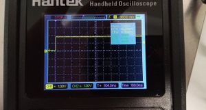
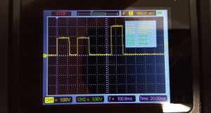
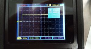
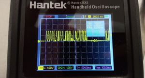
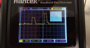
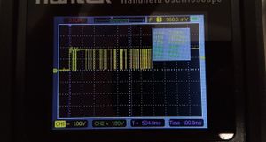
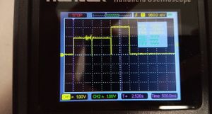
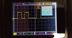
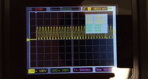
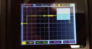
We did some probing around with an oscilloscope to see if there were any electrical differences between the good and bad boards. Both had identical measured crystal frequencies of 7.9 - 8.1 MHz and SIM7000 - ATmega382p baud rates of about 9540.
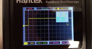
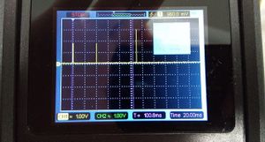
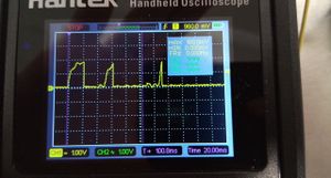
The one difference which was found was in the signals issued from the SIM 7000 to the SIM card on pins SIM_VDD, SIM_RST, SIM_CLK, and SIM_DATA. They are quite different. Notably the bad boards only power the SIM VDD line for 3 pulses of 24 ms long whereas the working boards good boards keep this line high. The measurements are taken after the AT+CFUN=1 command is issued in the above test sequence.
In doing some reading on the issue it seems to have been encountered before, with the conclusion that it likely a soldering issue, possible inside the SIM7000 modual, thus leaving little course for it to be able to repaired.
for boards with a SIM inserted
| PIN | Good Board | Bad Board |
|---|---|---|
| SIM_VDD | ||
| SIM_RST | ||
| SIM_CLK | ||
| SIM_DATA | No Reading |
for boards without a SIM inserted
| PIN | Good Board | Bad Board |
|---|---|---|
| SIM_VDD | ||
| SIM_RST | ||
| SIM_CLK | ||
| SIM_DATA | No Reading |
