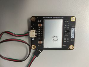
Out of Water Vel Sensor
We are developing a new velocity sensor which we hope will be able to detect the velocity of flowing water when placed outside of a flowing water body. The motivation for this is to ease the installation process, as this would allow the sensors to be installed without the removal of drain covers. The sensor should be capable of penetrating concrete drain covers and detecting the flow of water underneath.
21st January 2020
Microwave Doppler shift motion detectors can be sourced very affordably from the internet. Microwaves will readily penetrate thick concrete, but can also be easily blocked using a faraday cage to remove external noise. Our goal is to modify one of these sensors to detect not just motion, but the velocity of motion as well. We are currently using the Gravity Digital Microwave Sensor, which uses a 10.525 GHz microwave source.
The sensor sends out a signal and uses the phase difference between the outgoing and incoming waves due to doppler shift as a measure of velocity. hen a threshold velocity is observed, which is not useful for our application. The sensor outputs a digital high/low signal when a threshold velocity is observed. Our first task is to backtrack through the circuitry of the sensor, to probe the raw measured signal which measures the amplitude of the observed velocity.
By investigating the schematics for the sensor, we found that probing the pin 1 output of the LMV358 op-amp gave us a signal whose amplitude correlates well with velocity. We intend to find a calibration curve which will allow us to relate the amplitude of this signal to velocity.
The data taken below is a measure of the voltage output of the probed velocity sensor data over number of measurements. The measurement frequency is set to 5kHz. While no velocity is observed, the signal floats at around 208 which corresponds to approximately 1V. When agitated, the sensor outputs readings between 0 and 1023, (0-5V). Due to the signal floating at 208, we intend to use the time-averaged absolute difference between the current reading and 208 as a measure of velocity amplitude. Our next task will be remove the noise in the signal. The voltage output reading is clearly bounded by a reading of 1023 (5V). This will create some uncertainty when measuring very high velocities which we will also need to somehow avoid.
22nd January 2020
A low pass filter was integrated into the circuit to remove the high-frequency noise present in the data taking. Further removal of noise was accomplished by taking the weighted sum of the past 40 measurements (with higher priority to the latest measurements). Testing with flowing water will indicate whether or not this has removed enough noise to produce a meaningful calibration curve. We are also investigating toggling the sensitivity of the sensor, and choosing an appropriate material for the faraday cage which will block out external noise.

