Solar Panel
Solar panel integration with our BoSL board
Recently, BoSL team has been asked to deploy sensors to more remote areas which are significantly harder for us to do continuous battery changing. In order to ensure we have continuous data collection, the team has tried the low-cost solar panel available on the market. The works we have done around the solar panel design and trial are presented here for you to check.
Contents
Solar panel and voltage regulator
Tested parts purchased from core-electronics.com.au
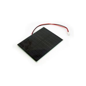
- 1W Soalr panel 80*100 from Seeed Studio (Link): AU$ 7.6
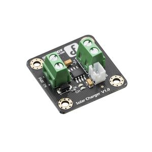
- Solar Lipo Charger 3.7V version (Link): AU$ 8.6
These two parts are selected based on the specification of our BoSL Board v0.4 and BoSL Nano Board data loggers (3.7V power supply and low power consumption). If your project requires a larger solar panel and higher voltage regulators, please visit the providers' website for more details.
Assigning the solar panel to our logger box
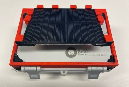
To fix the solar panel on the typical logger box the BoSL team is currently using, a 3D printed plastic frame was designed by our team member Grace Zhang (see the red colour frame in the figure below). The current version is a preliminary trial by just fixing the frame on the lid of the logger box by using hot glue. In the next version, we plan to have the solar panel frame properly screwed on the box.
Wire connection
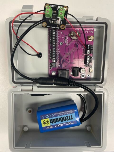
On the 3.7V Solar Lipo, there are three sets of power and ground connectors that we need to wire up. The top left corner screw terminal marked as "PWR IN" is to connect the solar panel. The top right corner screw terminal marked as "VOUT" is to connect with the power and the ground pins on the BoSL board. The bottom battery plug connects the solar panel with our lithium battery (in this case, the 11.2A Lithium battery the BoSL team has been using).
Initial testing results (continuously updating)
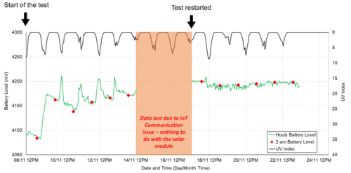
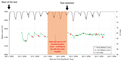
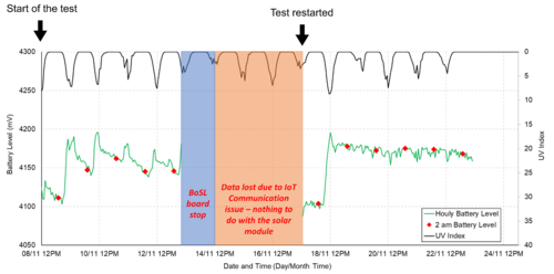
By using the setup described above, we have assembled three individual units with the solar panel and our BoSL Radar Velocity Sensor to test how well the solar panel performs. The three sensor units are placed on the green roof area of our Living laboratory with very open access to the sunlight. The results from 8th Nov to 23rd Nov are shown below. During this short period of time, we lost three days of data due to IoT communication technical issues (blame Crazydomain for putting us on a shared server with somebody else who got greylisted between 14th Nov and 17th Nov). The service was restored on 17th Nov, which is considered the restart day of this lab test.
As you can see from the results of all three trial units:
- their battery levels at 2AM (100% no charging happening at that time) have been mostly higher than 4.15V which is considered as fully charged
- The battery levels remained as high level before and after the telecommunication interruption (the tested logger uploaded data every 3 minutes before the interruption but only every 15 minutes after the interruption - therefore, 5 times higher power consumption before the interruption)
Future plan - the three testing units will be soon transferred to Melbourne's Western Treatment Plant for a longer term testing.
