Depth Sensor v2
6th March 2020
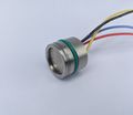
Taking measurements of water pressure can be used to calculate the depth at which the reading was taken. The sensor compares the pressure of the water to the atmospheric pressure allowing it to output a relative reading of the water pressure. This permits us to take an reasonably accurate measurement of the water depth.
We have two similar depth sensors that output either an analog or i2c signal both of which can be received by most micro-controller devices.
19th March 2020
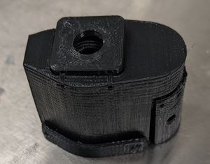
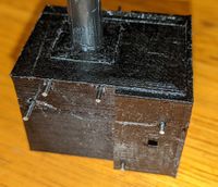
To allow for calibration and testing of the depth sensor, a 3D-printed housing was required. We also incorporated a EC mount into the design. The design had to be waterproof around the depth sensor, the EC prongs and the cable, each requiring o-rings to prevent water passage. It also had to have the depth sensor and EC prongs as close to the bottom of the probe as possible to provide reliable readings at a minimal depth of water. Multiple iterations had to be printed to ensure the tolerances of the 3D printer were accounted for.
22nd March 2020
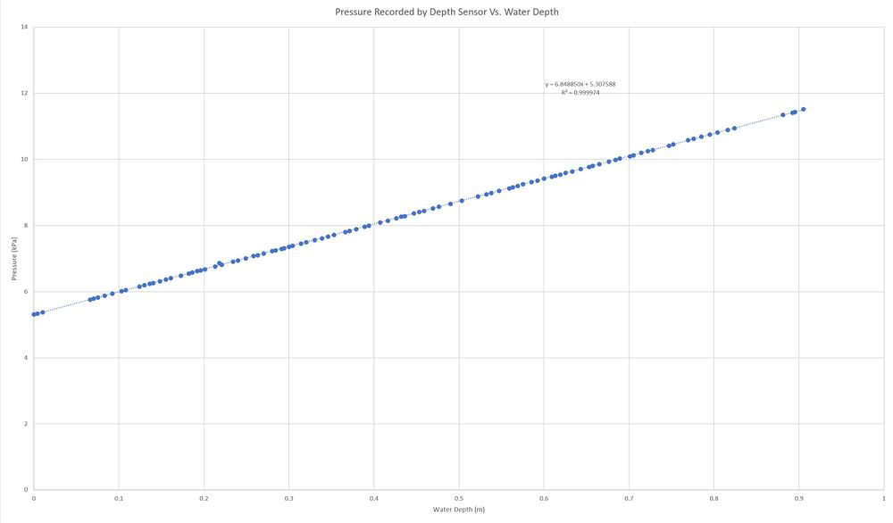
A calibration curve was created for the depth sensor in order to provide an accurate measurement of the water pressure and depth.
Recorded at 3.3 V and 18.90 C, the distance measurements were taken from the face of the sensing element that was 7mm from the bottom of a 19mm diameter tube. From this data we can conclude that the current formula f(x) should be modified to g(x) = 1.4324*f(x)-7.6024 to get an accurate readout of the pressure and h(x) = g(x)/9.81 to get the depth of the water from the sensing element.
If the sensor was exposed to just air on the sensing element, the output of the device was 5.30kPa, which is 15.14% of the maximum output of 35kPa and almost identical to the manufacturers specifications which were 15% of the maximum value.
30th March 2020
An experiment was undertaken to test the stability of the depth sensor. The results acquired were as follows:
| Time (Hours) | Water Depth (m) | Pressure (kPa) | Temperature (C) |
|---|---|---|---|
| 0.00 | 0.904 | 8.87 | 18.9 |
| 50.55 | 0.904 | 8.88 | 17.0 |
| 74.61 | 0.904 | 8.88 | 17.0 |
| 121.98 | 0.904 | 8.87 | 22.7 |
| 146.81 | 0.904 | 8.88 | 22.7 |
| 169.57 | 0.904 | 8.88 | 22.7 |
The fluctuations in the results may be due to slight variations in the water level due to small volumes of the water evaporating and being replaced to maintain a constant water level. The temperature of the water may have also have affected the results.
13th April 2020
Further experimentation was carried out to check the precision and accuracy of the pressure sensor. The results were as follows
| Time (Hours) | Water Depth (m) | Pressure (kPa) | Temperature (C) |
|---|---|---|---|
| 0.00 | 0.905 | 8.8836 | 21.0097 |
| 23.59 | 0.905 | 8.8818 | 21.4496 |
| 47.11 | 0.905 | 8.8885 | 21.1009 |
| 71.61 | 0.905 | 8.8873 | 20.9945 |
| 95.05 | 0.905 | 8.8822 | 20.9065 |
| 118.64 | 0.905 | 8.8870 | 20.3276 |
| 142.24 | 0.905 | 8.8812 | 19.9485 |
| 163.85 | 0.905 | 8.8842 | 20.3499 |
| 191.00 | 0.905 | 8.8846 | 20.4340 |
| 216.71 | 0.905 | 8.8853 | 20.7310 |
| 240.00 | 0.905 | 8.8859 | 20.8577 |
| 263.64 | 0.905 | 8.8883 | 20.1381 |
| 287.93 | 0.905 | 8.8852 | 20.2627 |
The slight variation was most likely due to slight changes in the water depth within a millimeter. Therefore, the pressure is accurate within ±5Pa or ±0.510mm. The experimentation will continue, and a BME280 sensor will be used to accurately scale the temperature.
The current iteration of the depth sensor housing is waterproof under low water pressures, however, it does start leaking when the water pressure increases.
Using an O-Ring in between the main housing and the top cover greatly increased how waterproof the design was.
To make the design more waterproof, the O-Rings must be forced into the a smaller area. This will be done by further reducing or eliminating space allowed for the O-Rings down to a pinch point where the O-Rings will (hopefully) completely seal housing!
A PCB was also designed to hold an ATmega328p-au to convert the signals received from the depth sensor and EC into a single data stream and a LN2985 3.3V regulator.
The pins for programming are currently through hole pins, however in future they may be changed to pads to allow more room for proper placement of the depth sensor and cable pins. This design will only work, given that all pins (excluding the EC pins) are flexible. The ECS pin is just in case of another analog input being required. The external crystal was taken out of the circuit and the internal 8MHz clock will be used instead, this should not have a great effect of the performance of the device as speed is not essential. When the exact layout of the pins is known for the depth sensor, a second version will be created that will have the depth sensor and cable pins centralized around the hole in the board (for the back of the depth sensor) and have surface mount pads for the programming pins instead of through-hole mounts to occupy less space of the board.


