Connect Commercial Sensor to BoSL
Contents
Introduction
While our self-developed BoSL low-cost sensors offer versatile, flexible, and affordable solutions to the highly spatially distributed real-time water monitoring campaigns, the high-end commercial sensors are sometimes still needed in accordance with the special requirements of these monitoring campaigns. Usually, a data logger is required to couple with these sensors at a monitoring location to collect and store the sensor data. However, these expensive data loggers are not able to directly transmit sensor data to the internet in real time but rely on manual download on the site.
This problem can be solved by our BoSL microcontrollers. BoSL microcontrollers is capable of controlling and reading the high-end commercial sensors, as well as sending the data to the internet after each sensor reading, without the need of a separate data logger.
This wiki page introduces how BoSL microcontroller functions as an IoT-enabled data logger for the high-end commercial sensors, using BoSL Board, and Greenspan Water Depth Sensor (PS-7000A) and Turbidity Sensor (TS-1000A) as an example.
Hardware
Both PS-7000A and TS-1000A are analogue sensors with 4-20mA signal current output, but the PS-7000A is a 2-Wire Loop Powered sensor while TS-1000A is a 4-Wire Fully Isolated sensor. This section aims to provide instructions on how to wire up these two kinds of sensors.
In addition to the BoSL Board, signal relays (with low coil voltage) and resistors are required to control both sensors and help to read the sensor measurement. One BoSL Board can be used to connect to both sensors if they are installed at the same location.
TS-1000A Turbidity Sensor (4-Wire Fully Isolated)
4-Wire Fully Isolated sensor use independent 4-20mA signal cables (+ive and -ive) and power cables (+ive and -ive). The following figure shows the relationships between each component.
In this case of turbidity sensor, two relays are used as the switches. One relay is used to switch on/off the power for the commercial sensor, and the other replay is used to trigger the wiper to clean the sensor lens. The output circuits are open by default, and they can be opened/closed by the sending input signals from the BoSL I/O pins. Two I/O pins on the BoSL Board are needed to control one relay. Since the relays are low-voltage latching relays, they require no continuous power consumption but a signal pulse.
To read the sensor measurement after switching on the sensor, a resistor is connected to the positive and negative 4-20mA signal cables in series. A 100-ohm resistor would convert the signal to 0.4-2 volts of voltage across its two terminals, which can be read by BoSL Board using the analog reading function.
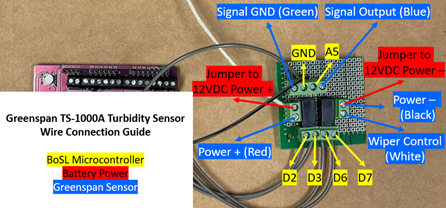
The following tables and figure show how exactly everything is wired up in the hardware setup. In application, a PCB breadboard is used with relays, resistor, and screw terminals soldered on it. We call it interface board and it makes the installation and maintenance work in the field easier.
BoSL Board |
Interface Board |
|---|---|
D2 |
Relay for Sensor Power – Input Positive |
D3 |
Relay for Sensor Power – Input Negative |
D6 |
Relay for Wiper Control – Input Positive |
D7 |
Relay for Wiper Control – Input Negative |
A5 |
100-Ohm Resistor – Positive |
GND |
100-Ohm Resistor – Negative |
TS-1000A Sensor |
Interface Board |
|---|---|
Red (Power+) |
Relay for Sensor Power – Output Contact A |
Black (Power-) |
Relay for Wiper Control – Output Contact B |
White (Wiper Trigger) |
Relay for Wiper Control – Output Contact A |
Blue (Signal+) |
100-Ohm Resistor – Positive |
Green (Signal GND) |
100-Ohm Resistor – Negative |
12V Battery |
Interface Board |
|---|---|
Red (Power+) |
Relay for Sensor Power – Output Contact B |
Black (Power-) |
Relay for Wiper Control – Output Contact B |
PS-7000A Depth Sensor (2-Wire Loop Powered)
This type of sensor does not have independent power negative and signal negative cables. Instead, its power current is also the 4-20mA signal current, as they share a same loop. Wiring up the 2-wire sensors is simpler than the 4-wire sensors with less cables needed. However, using relay to switch on/off the sensor and using resistor to read the sensor measurement remain the same for the 2-wire sensors. The following figure shows the relationships between each component.
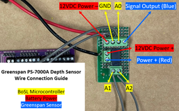
The following tables and figure show how exactly everything is wired up in the hardware setup.
BoSL Board |
Interface Board |
|---|---|
A1 (used as digital output pin) |
Relay for Sensor Power – Input Positive |
A2 (used as digital output pin) |
Relay for Sensor Power – Input Negative |
A0 |
100-Ohm Resistor – Positive |
GND |
100-Ohm Resistor – Negative |
PS-7000 Sensor |
Interface Board |
|---|---|
Red (Power+) |
Relay for Sensor Power – Output Contact A |
Blue (Signal+) |
100-Ohm Resistor – Positive |
12V Battery |
Interface Board |
|---|---|
Red (Power+) |
Relay for Sensor Power – Output Contact B |
Black (Power-) |
100-Ohm Resistor – Negative |
Software
Using BoSL Board as the data logger for commercial sensors remains the flexibility to meet the monitoring requirements, as we can easily configure the sensor measurement and wiper trigger intervals.
All I/O pins connected to the relay input circuits are set as OUTPUT. To switch on the sensor power/lens wiper, pull the I/O pin connected to the positive input of the relay to HIGH (3.3V) momentarily and the pull it back to LOW (0V). Likewise, to switch off the sensor power/lens wiper, pull I/O pin connected to the negative input of the relay to HIGH (3.3V) momentarily and the pull it back to LOW (0V).
The analog pin connected to the positive side of the resistor is set as INPUT to read the signal voltage across the resistor using analogRead() function. Convert the measured voltage to the 4-20mA signal current using the Ohm’s Law (I = V/R). Then, convert signal current to the actual sensor reading using the factory data on the manual or calibration data.
Please note that, the ADC (Analog-to-Digital Converter) on the BoSL Board is 8-bit ADC and has an analog reading resolution of 1024, which in turn result in undesirable high increment and low accuracy in the sensor data. This may not meet the accuracy needed in some monitoring scenarios. To increase analog reading resolution as well as the sensor measurement resolution, the nanoBoSL Board with 12-bit ADC and an analog reading range of 4096 could be used. Alternatively, 4-20mA Current Loop Receiver with I2C Interface on the market can be used as BoSL Board supports I2C communication. Also, the RX-TX serial pins on the BoSL Board can be used for some commercial sensors that use the data communication protocols (such as RS-232) other than the analogue 4-20mA current loop.
The data uploading process is the same as all other low-cost BoSL sensors. SIM card and a destination server are needed.
In the cases where real-time data uploading is not required or not possible, the BoSL Board can still function as the commercial data logger, thanks to the built-in real-time clock and SD card module.


