Difference between revisions of "Turbidity Sensor"
Jump to navigation
Jump to search
| Line 6: | Line 6: | ||
The whole process of the design is followed by the paper you sent to me. Now the turbidity sensor is connecting to the Arduino and we can get the signal. | The whole process of the design is followed by the paper you sent to me. Now the turbidity sensor is connecting to the Arduino and we can get the signal. | ||
| + | <br> | ||
[[File:Image004.png]] | [[File:Image004.png]] | ||
Currently, holes on the box are drilled by hand, next step, the new box with holes will be printed by the 3D printer which will be more accurate in angle. Also, I have asked Luke to order some fixed turbidity solution for further testing and calibration. | Currently, holes on the box are drilled by hand, next step, the new box with holes will be printed by the 3D printer which will be more accurate in angle. Also, I have asked Luke to order some fixed turbidity solution for further testing and calibration. | ||
| + | <br> | ||
<b> 5th November 2019</b> | <b> 5th November 2019</b> | ||
Revision as of 20:33, 4 November 2019
3th November 2019
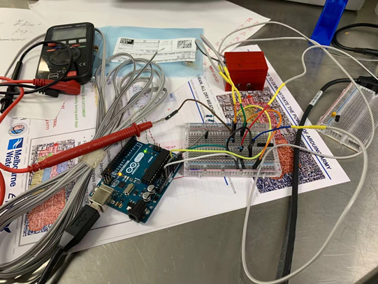
As we got the parts of the turbidity sensor this Friday, The preliminary version of the turbidity sensor has already designed and tested. Luke was beside me all the time and gave me a lot of help.
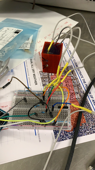
The whole process of the design is followed by the paper you sent to me. Now the turbidity sensor is connecting to the Arduino and we can get the signal.

Currently, holes on the box are drilled by hand, next step, the new box with holes will be printed by the 3D printer which will be more accurate in angle. Also, I have asked Luke to order some fixed turbidity solution for further testing and calibration.
5th November 2019
