Difference between revisions of "BoSL Board v0.3"
| Line 4: | Line 4: | ||
This little beauty costs less than an Arduino and Sim5320a put together, yet it comes already assembled, runs on 4v, is ultra low power consuming (we removed all the overheads of the off the shelf arduinos) and can send data via the CAT-M1 or NB-IoT networks! We estimate that these things can log each minute for over 12months! | This little beauty costs less than an Arduino and Sim5320a put together, yet it comes already assembled, runs on 4v, is ultra low power consuming (we removed all the overheads of the off the shelf arduinos) and can send data via the CAT-M1 or NB-IoT networks! We estimate that these things can log each minute for over 12months! | ||
| − | ==== BoSL | + | ==== BoSL BOARD V0.3 PIN LAYOUT ==== |
| + | ATmega328P Pin Number Arduino IDE pin Internal Use Application Notes | ||
| + | 1 Reset RST Pull Low to reset Arduino | ||
| + | 2 D0 USB RX Free for use when no micro-USB connected | ||
| + | 3 D1 USB TX Free for use when no micro-USB connected | ||
| + | 4 D2 SIM7000 RX Not Available for use | ||
| + | 5 D3 SIM7000 TX Not Available for use | ||
| + | 6 D4 SIM7000 On/Off Not Available for use | ||
| + | 7 VCC VCC N/A | ||
| + | 8 GND GND N/A | ||
| + | 9 Crystal XTAL Not Available for use | ||
| + | 10 Crystal XTAL Not Available for use | ||
| + | 11 D5 SIM7000 DTR Not Available for use | ||
| + | 12 D6 None Free for use | ||
| + | 13 D7 None Free for use | ||
| + | 14 D8 None Free for use | ||
| + | 15 D9 None Free for use | ||
| + | 16 D10 SD Chip Select Free for use with no SD card inserted | ||
| + | 17 D11 SD MOSI Free for use with no SD card inserted | ||
| + | 18 D12 SD MISO Free for use with no SD card inserted | ||
| + | 19 D13 SD Serial Clock Free for use with no SD card inserted | ||
| + | 20 VCC VCC N/A | ||
| + | 21 Aref None Free for use | ||
| + | 22 GND GND N/A | ||
| + | 23 A0 None Free for use | ||
| + | 24 A1 None Free for use | ||
| + | 25 A2 None Free for use | ||
| + | 26 A3 None Free for use | ||
| + | 27 A4 SDA Free for use when not operating I2C bus | ||
| + | 28 A5 SCL Free for use when not operating I2C bus | ||
Revision as of 16:30, 25 November 2019
BOSL BOARD - THE ULTRA LOW POWERED IOT LOGGING DEVICE
This little beauty costs less than an Arduino and Sim5320a put together, yet it comes already assembled, runs on 4v, is ultra low power consuming (we removed all the overheads of the off the shelf arduinos) and can send data via the CAT-M1 or NB-IoT networks! We estimate that these things can log each minute for over 12months!
Contents
BoSL BOARD V0.3 PIN LAYOUT
ATmega328P Pin Number Arduino IDE pin Internal Use Application Notes 1 Reset RST Pull Low to reset Arduino 2 D0 USB RX Free for use when no micro-USB connected 3 D1 USB TX Free for use when no micro-USB connected 4 D2 SIM7000 RX Not Available for use 5 D3 SIM7000 TX Not Available for use 6 D4 SIM7000 On/Off Not Available for use 7 VCC VCC N/A 8 GND GND N/A 9 Crystal XTAL Not Available for use 10 Crystal XTAL Not Available for use 11 D5 SIM7000 DTR Not Available for use 12 D6 None Free for use 13 D7 None Free for use 14 D8 None Free for use 15 D9 None Free for use 16 D10 SD Chip Select Free for use with no SD card inserted 17 D11 SD MOSI Free for use with no SD card inserted 18 D12 SD MISO Free for use with no SD card inserted 19 D13 SD Serial Clock Free for use with no SD card inserted 20 VCC VCC N/A 21 Aref None Free for use 22 GND GND N/A 23 A0 None Free for use 24 A1 None Free for use 25 A2 None Free for use 26 A3 None Free for use 27 A4 SDA Free for use when not operating I2C bus 28 A5 SCL Free for use when not operating I2C bus
SIM7000 SIM CARD COMMUNITCATION ISSUE
2019/11/21:
There has been an issue where some of our boards aren't recognising the SIM cards, and so can't upload any data. To detect is if the issue is present the following AT command sequence can be sent.
GOOD RESPONSE
| Command | Response |
|---|---|
| AT+CFUN=0 | |
| +CPIN: NOT READY | |
| OK | |
| AT+CFUN=1 | |
| OK | |
| +CPIN = READY | |
| SIM READY |
BAD RESPONSE
| Command | Response |
|---|---|
| AT+CFUN=0 | |
| +CPIN: NOT READY | |
| OK | |
| AT+CFUN=1 | |
| OK | |
| +CPIN: NOT INSERTED |
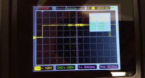
We did some probing around with an oscilloscope to see if there were any electrical differences between the good and bad boards. Both had identical measured crystal frequencies of 7.9 - 8.1 MHz and SIM7000 - ATmega382p baud rates of about 9540.
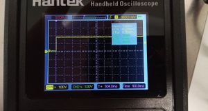
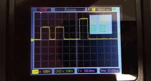
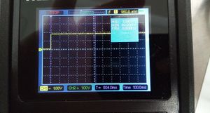
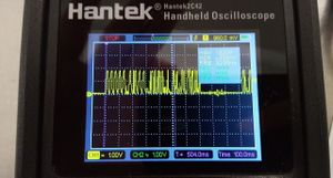
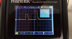
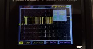
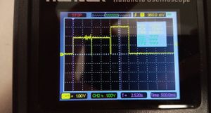
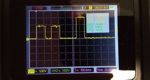
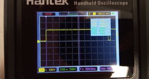
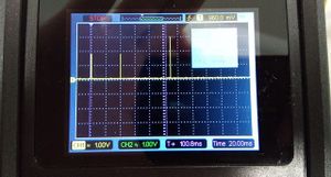
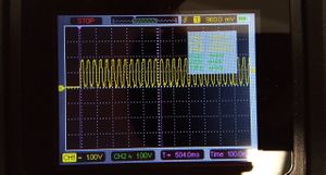
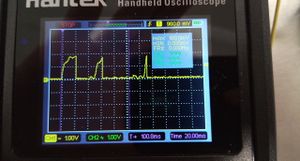
The one difference which was found was in the signals issued from the SIM 7000 to the SIM card on pins SIM_VDD, SIM_RST, SIM_CLK, and SIM_DATA. They are quite different. Notably the bad boards only power the SIM VDD line for 3 pulses of 24 ms long whereas the working boards good boards keep this line high. The measurements are taken after the AT+CFUN=1 command is issued in the above test sequence.
In doing some reading on the issue it seems to have been encountered before, with the conclusion that it likely a soldering issue, possible inside the SIM7000 modual, thus leaving little course for it to be able to repaired.
for boards with a SIM inserted
| PIN | Good Board | Bad Board |
|---|---|---|
| SIM_VDD | ||
| SIM_RST | ||
| SIM_CLK | ||
| SIM_DATA | No Reading |
for boards without a SIM inserted
| PIN | Good Board | Bad Board |
|---|---|---|
| SIM_VDD | ||
| SIM_RST | ||
| SIM_CLK | ||
| SIM_DATA | No Reading |
