Difference between revisions of "Human Comfort Supplementary"
Jump to navigation
Jump to search
(→Wiring) |
(→Wiring) |
||
| Line 1: | Line 1: | ||
=Wiring= | =Wiring= | ||
Here's the wiring for the human comfort sensor. The connection that we have done are following the cable colors of this chart | Here's the wiring for the human comfort sensor. The connection that we have done are following the cable colors of this chart | ||
| + | |||
If the One wire sensor that is used aren't the parasitic power type, add a 1k resistor between the Data and Vin. | If the One wire sensor that is used aren't the parasitic power type, add a 1k resistor between the Data and Vin. | ||
| + | |||
[[File:HC Wiring.png|600px]] | [[File:HC Wiring.png|600px]] | ||
| + | |||
| + | |||
| + | The wind meter requires a desoldering on the original power module that is originally attached to the board. After its being removed, just attached wires to the connector point. | ||
| + | The connection for the wires are : | ||
| + | - 5V to pin 1 | ||
| + | - GND to pin 2 | ||
| + | - Vout to pin 3 | ||
| + | {| class="wikitable" | ||
| + | |- | ||
| + | ! Windmeter Board !! Connector | ||
| + | |- | ||
| + | | [[File:Windmeter Board.jpg|thumb]] || | ||
| + | [[File:Windmeter Connector.png|thumb]] | ||
| + | |} | ||
=Program Code= | =Program Code= | ||
Revision as of 01:52, 8 February 2023
Wiring
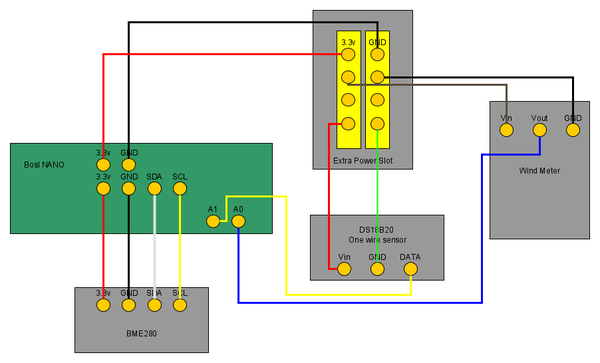
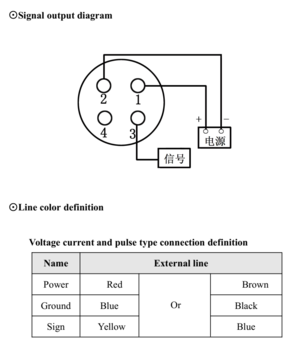
Here's the wiring for the human comfort sensor. The connection that we have done are following the cable colors of this chart
If the One wire sensor that is used aren't the parasitic power type, add a 1k resistor between the Data and Vin.
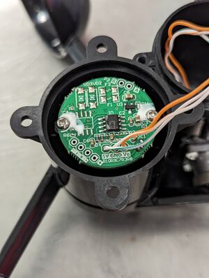
The wind meter requires a desoldering on the original power module that is originally attached to the board. After its being removed, just attached wires to the connector point.
The connection for the wires are :
- 5V to pin 1
- GND to pin 2
- Vout to pin 3
| Windmeter Board | Connector |
|---|---|
Program Code
Final Program File: File:WeatherStation-nanoLoop0.4.1 - simbase.ino


