Difference between revisions of "Human Comfort Supplementary"
| Line 37: | Line 37: | ||
==Program Subroutine explanation== | ==Program Subroutine explanation== | ||
| − | nRFrst = reset the nrf chips | + | nRFrst = reset the nrf chips |
| − | SDsetup = initialize the SD card module | + | SDsetup = initialize the SD card module |
| − | mobileStart = Start running all the AT commands needed to initialize the LTE connection | + | mobileStart = Start running all the AT commands needed to initialize the LTE connection |
| − | pull_net_time = get current time from the web at GMT 0, it also captures the timezone but this value isn't used in our application | + | pull_net_time = get current time from the web at GMT 0, it also captures the timezone but this value isn't used in our application |
| − | filename = generates the file name in the SD card for numbering purposes | + | filename = generates the file name in the SD card for numbering purposes |
| − | sensor_scan = get data from all of the sensor | + | sensor_scan = get data from all of the sensor |
| − | CBCread = get battery voltage reading | + | CBCread = get battery voltage reading |
| − | sd_log = log the captured data into the sd card | + | sd_log = log the captured data into the sd card |
| − | nRFWake = wake up the nrf chip | + | nRFWake = wake up the nrf chip |
| − | read_sd = read the previous generated file in the sd card and start the upload sequence to the ftp server | + | read_sd = read the previous generated file in the sd card and start the upload sequence to the ftp server |
| − | sleepy = set the board to sleep mode for a specific amount of time | + | sleepy = set the board to sleep mode for a specific amount of time |
Latest revision as of 02:30, 8 February 2023
Wiring
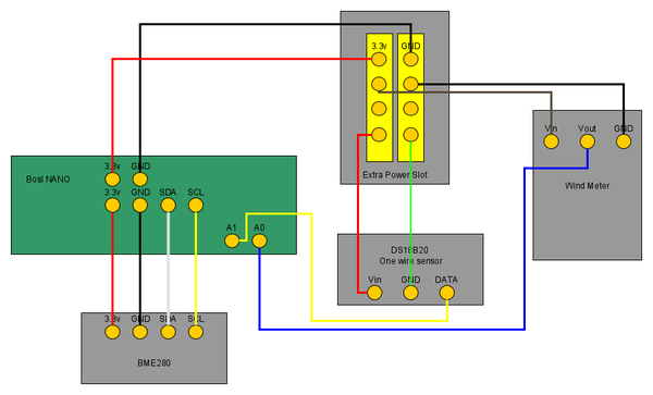
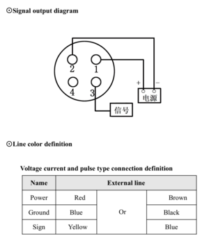
Here's the wiring for the human comfort sensor. The connection that we have done are following the cable colors of this chart
If the One wire sensor that is used aren't the parasitic power type, add a 1k resistor between the Data and Vin.
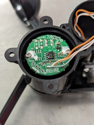
The wind meter requires a desoldering on the original power module that is originally attached to the board. After its being removed, just attached wires to the connector point.
The connection for the wires are :
- 5V to pin 1
- GND to pin 2
- Vout to pin 3
| Windmeter Board | Connector |
|---|---|
Program Code
Final Program File: File:WeatherStation-nanoLoop0.4.1 - simbase.ino
Sensor Testing Program: File:WeatherStation-SensorOnly.ino
The current version of the code use simbase as the main simcard, if there' any need to change to another card just do a change in line 270. Change the simbase into the new simcard APN:
ercode = sendATcmd("AT+CGDCONT=0,\"IP\",\"simbase\"", "OK");
The upload timing of the code are currently being set to take every 1 hour of data measuring. If it need to be change to the previous method of uploading (2 times every day), there's commented line from 441 - 467 that do just that. Just uncomment that line and comment or delete the 1 hour upload timing code which is on line 468 - 475.
Program Subroutine explanation
nRFrst         = reset the nrf chips
SDsetup        = initialize the SD card module
mobileStart    = Start running all the AT commands needed to initialize the LTE connection
pull_net_time  =  get current time from the web at GMT 0, it also captures the timezone but this value isn't used in our application
filename       = generates the file name in the SD card for numbering purposes
sensor_scan    = get data from all of the sensor
CBCread        = get battery voltage reading
sd_log         = log the captured data into the sd card
nRFWake        = wake up the nrf chip
read_sd        = read the previous generated file in the sd card and start the upload sequence to the ftp server
sleepy         = set the board to sleep mode for a specific amount of time


