Difference between revisions of "Turbidity Sensor"
Jump to navigation
Jump to search
| Line 1: | Line 1: | ||
| − | |||
| − | |||
| − | |||
| − | |||
| − | |||
| − | |||
| − | |||
| − | |||
| − | |||
| − | |||
| − | |||
| − | |||
| − | |||
| − | |||
| − | |||
| − | |||
| − | |||
| − | |||
| − | |||
| − | |||
| − | |||
| − | |||
| − | |||
| − | |||
| − | |||
| − | |||
| − | |||
| − | |||
| − | |||
| − | |||
| − | |||
| − | |||
<b> 12th November 2019</b> | <b> 12th November 2019</b> | ||
So we finally made some nice progress with the Turbidity Sensor design. | So we finally made some nice progress with the Turbidity Sensor design. | ||
| Line 36: | Line 4: | ||
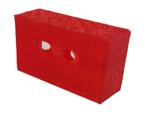
First step was to print our case using our 3D printer. Here it is: | First step was to print our case using our 3D printer. Here it is: | ||
[[File:TurbBoxV0.1.png|300px]] | [[File:TurbBoxV0.1.png|300px]] | ||
| + | |||
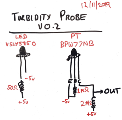
| + | Next step was to test out some hardware for the little guy. We bought two main things: (1) a LED that puts out 850nm wavelength and (2) a phototransistor. The details of the connection we used is here: | ||
| + | [[File:TurbV0.1Circuitdiagram.png|400px]] | ||
Revision as of 04:08, 12 November 2019
12th November 2019 So we finally made some nice progress with the Turbidity Sensor design.
First step was to print our case using our 3D printer. Here it is:

Next step was to test out some hardware for the little guy. We bought two main things: (1) a LED that puts out 850nm wavelength and (2) a phototransistor. The details of the connection we used is here:
