Difference between revisions of "Rain gauge"
| Line 173: | Line 173: | ||
Firstly, we changed the design of the tipping bucket mechanism by replacing the base container with a tipping bucket stand. In the last version of the design, we calibrated the amount of water flipped by the tipping bucket by changing the position of the axle, but the self-lock nut failed to secure the axle of the tipping bucket adequately, causing the bucket to move during shipment or vibration. Consequently, the calibration results were affected. This new stand fixes the height position of the tipping bucket axle, ensuring the bucket will not move vertically over time. Thus, we changed the calibration method from moving the tipping bucket axle to using a screw adjustment. Simultaneously, this method reduces the difficulty and time of calibration. | Firstly, we changed the design of the tipping bucket mechanism by replacing the base container with a tipping bucket stand. In the last version of the design, we calibrated the amount of water flipped by the tipping bucket by changing the position of the axle, but the self-lock nut failed to secure the axle of the tipping bucket adequately, causing the bucket to move during shipment or vibration. Consequently, the calibration results were affected. This new stand fixes the height position of the tipping bucket axle, ensuring the bucket will not move vertically over time. Thus, we changed the calibration method from moving the tipping bucket axle to using a screw adjustment. Simultaneously, this method reduces the difficulty and time of calibration. | ||
| − | ==== Integrate the | + | ==== Integrate the stand with the main body ==== |
Secondly, we changed the connection between the main body and the stand from 'studs' to screw fixation, making the connection stronger. The previous studs were too easy to break, preventing the body and base from fitting and connecting properly. | Secondly, we changed the connection between the main body and the stand from 'studs' to screw fixation, making the connection stronger. The previous studs were too easy to break, preventing the body and base from fitting and connecting properly. | ||
| + | ===== ''Fixed reed switch position ''===== | ||
| + | We have determined the optimum reed switch position by constantly adjusting the distance between the magnet and the reed switch. The reed switches are perfectly inserted into the grooves by 3d printing of the grooves, thus ensuring that every rain gauge produced has the same position of the reed switches. | ||
| + | |||
| + | =====''Existing problems ''===== | ||
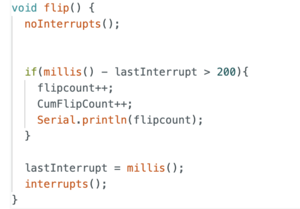
| + | According to the principle of the reed switch, the reed switch closes when the magnet passes over it, but there is a problem of duplicate count in our code. It might be cuased by bouncing. When a reed switch closes or opens, it can sometimes bounce rapidly between the on and off states before settling. This bouncing effect can be misinterpreted as multiple tipping events. So we used a debounce algorithm in our code to solve this problem. | ||
| + | |||
| + | [[File:Bouncing code.png|thumb|center|debounce function]] | ||
==== Integrate the funnel with the main body ==== | ==== Integrate the funnel with the main body ==== | ||
Revision as of 13:13, 12 October 2023
This section shows the journey for making our 3D print rain gauge!
Contents
Design journey
We didn't start from scratch - we work on Suromark's version (referred as original design in the following) and we did some changes to that:
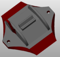
First, we noticed that the tipping bucket can get stuck to the pivot if operated overnight, so we changed the flipper with 0.6 mm clearance. Secondly, we noticed that not all of the water in the bucket can escape when tipping. We compared with the standard tipping bucket rain gauge design, and we added a sharp edge and made some "swale" in the bucket to help divert water when tipping:
Thirdly, we found water can be soaked into the tipping bucket during long-time operation so we changed the 3D print from 30% infill to 100% infill;
In the end, we found that the tipping volume can change from time to time. We found during the overnight operation, a small amount of water from splashing or dripping can stay on the rain gauge base, which probably increases the friction between the base and bucket, therefore influencing the tipping volume. In that case, we changed the base design - to make water can easily escape so the tipping volume is consistent.
3D print files
Thanks Stephen for designing and editing the files!
Nano Board code
Thanks Luke(Baiqian) Shi for the coding :)
File:Nano Rainguage Sender.ino
Assembly instructions
The following video outlines the process required to assemble the gauge and to connect it to a logging system.
Application
We have used these rain gauges in Xixi Shi's lab-wetlands to monitor the outflow rate. There are 6 wetlands in total, and we have equipped each wetland outlet with a rain gauge to monitor the outflow rate.
This is the calibration for each rain gauge tipping bucket:
| Rain gauge tipping volume(ml) | Feb 16 3pm | Feb 17 11am | overnight difference (%) |
|---|---|---|---|
| R1 | 2.8 | 2.8 | 2 |
| R2 | 2.9 | 2.9 | 2 |
| R3 | 2.8 | 3.1 | 9 |
| R4 | 2.9 | 3.1 | 7 |
| R5 | 3 | 3 | -1 |
| R6 | 3 | 2.9 | 2 |
New Design journey
Our design is based on the Giovanni Aggiustatutto's version. We made some changes to it:
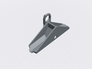
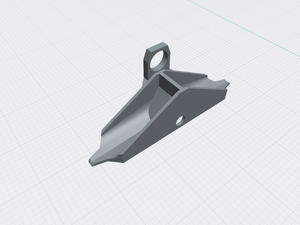
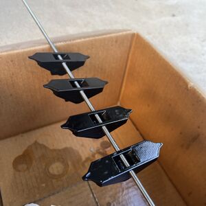
Firstly, we noticed that this tipping bucket had the same issue as Xixi's design, which was that water could not escape when tipping. To address this, we added a sharp edge and slope trench to help the water escape while tipping.
Secondly, based on Xixi Shi's experience, we found that the PLA filament absorbs water in a humid environment, which can alter the flipper's weight and tipping value. Therefore, we decided to use other waterproof materials such as PETG and PP filament to print the flipper.
Thirdly, we added a base at the bottom of the rain gauge container to ensure that rainwater can escape better after tipping.
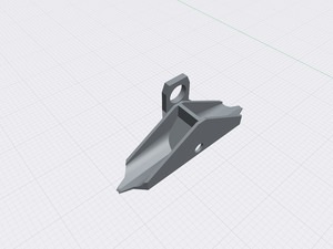
Flipper (tipping bucket)
We made several versions of changes to the sharp edges and slopes to improve water drainage.
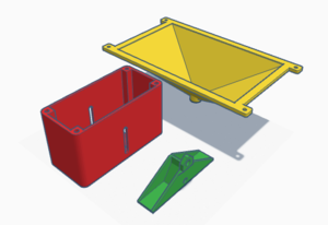
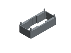
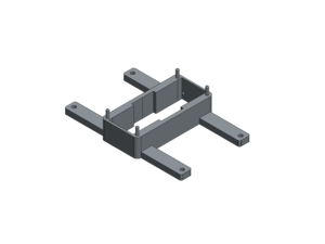
Stand
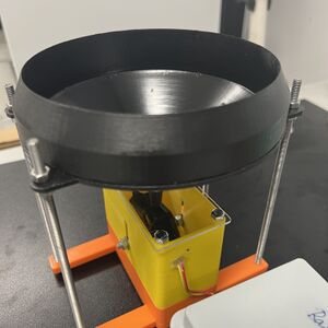
We added an stand under the base container to raise the height without using threaded rod.
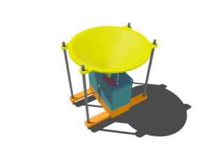
Additionally, we removed the flat aluminum profile that Giovanni used under the container and added four arms to the stand, which connect the funnel and rain gauge box using M5 stainless steel stranded rods and some pieces of M5 self-locking nuts and washers.
Funnel
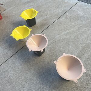
We changed the funnel shape form rectangular cone to a circular cone. A circular funnel allows for more efficient collection of rainwater compared to a rectangular funnel. The shape of a circle allows for better distribution of the incoming rainwater, ensuring a more accurate measurement.
Assembly
All printing parts are including in below file.
Testing
Printing material
We used PLA and PETG to print the flipper and test its waterproof effect. First, we measured thier dry weight and put them in the water overnight and then measured the wet weight separately. The results show that PETG and PLA are both absorb water, both of them can not be fully waterproof.
| Material | Dry weight | Wet weight | Different | % |
|---|---|---|---|---|
| PETG | 10.0903 | 10.1776 | 0.0873 | 0.865% |
| PLA | 8.5891 | 8.6976 | 0.1085 | 1.263% |
Therefore, we applied a clear, protective finish to the printed components using Rust-Oleum 2X Ultra Cover Satin Spray to achieve waterproof performance.
Tipping value
We need to find the rainfall in millimeters in height, therefore, we achieved 2 ml of water per flip by constantly adjusting the height of the flipper.
Coding
Hall effect Sensor
As the Arduino only allows one program running at a time, in the case of flip happened during the uploading process, an additional MicroBoard is used as an counter to help solve this issue. The connection is shown as follow:
The code for using the hall effect sensor is attached here:
File:Newdesign Rainguage Sender.txt
File:Newdesign Rainguage logger.ino
Reed Switch
Since the rain guage is aimed to be used at field condition. The previous hall effect sensor version is not satisfied as the logging sensor always needs to listen from the sending sensor, which is large battery consuming. Therefore, we are looking for some sensors that can support the sleep function. The reed switch is then selected.
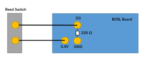
The connection is shown as follows:
The code for using the reed switch is attached here:
VERSION 1. File:Rainguage logger Hologram.ino VERSION 2: File:Raingauge.ino VERSION 3: File:Raingauge v3.ino
Problem
The biggest problem with this version of the design is that the tipping bucket shifts too easily, so the reed switch cannot trigger the movement during the rainfall event. The self-lock nut fails to secure the axle of the flip bucket adequately, causing it to move during shipment. As a result, this movement alters the calibration result, making it difficult for the reed switch to be triggered.
Also, the connection points of the stand are too weak and small, breaking very easily.
Therefore, the new design incorporates the following points:
- Fix the axle height of the tipping bucket.
- Integrate the stand with the main body.
- Integrate the funnel with the main body.
- Engergy saving.
New Design version 2
We refer to the design of commercial rain gauge, Simplified the assembly process and calibration process.
Fix the axle height of the tipping bucket
Firstly, we changed the design of the tipping bucket mechanism by replacing the base container with a tipping bucket stand. In the last version of the design, we calibrated the amount of water flipped by the tipping bucket by changing the position of the axle, but the self-lock nut failed to secure the axle of the tipping bucket adequately, causing the bucket to move during shipment or vibration. Consequently, the calibration results were affected. This new stand fixes the height position of the tipping bucket axle, ensuring the bucket will not move vertically over time. Thus, we changed the calibration method from moving the tipping bucket axle to using a screw adjustment. Simultaneously, this method reduces the difficulty and time of calibration.
Integrate the stand with the main body
Secondly, we changed the connection between the main body and the stand from 'studs' to screw fixation, making the connection stronger. The previous studs were too easy to break, preventing the body and base from fitting and connecting properly.
Fixed reed switch position
We have determined the optimum reed switch position by constantly adjusting the distance between the magnet and the reed switch. The reed switches are perfectly inserted into the grooves by 3d printing of the grooves, thus ensuring that every rain gauge produced has the same position of the reed switches.
Existing problems
According to the principle of the reed switch, the reed switch closes when the magnet passes over it, but there is a problem of duplicate count in our code. It might be cuased by bouncing. When a reed switch closes or opens, it can sometimes bounce rapidly between the on and off states before settling. This bouncing effect can be misinterpreted as multiple tipping events. So we used a debounce algorithm in our code to solve this problem.
Integrate the funnel with the main body
Additionally, the design maintains the original circular funnel design but replaces the four support rods with a basic cylinder topped with a funnel. This cylindrical funnel fits over the base to create an enclosed, watertight space inside. Ensure that the box only receives water from the top funnel.
Energy saving
We originally had an external resistor on the Arduino board, but it still consumed too much power for our low-power device. So, we used an internal pull-up resistor to save power. When a pull-up resistor is employed in an input pin, it reduces the current flow when the reed switch is not activated. This minimizes power consumption, especially in battery-powered applications, by preventing a continuous flow of current through the input pin. To do this, we enabled the internal pull-up resistor on pin 3.


