Difference between revisions of "Depth Sensor v2"
| (3 intermediate revisions by 2 users not shown) | |||
| Line 307: | Line 307: | ||
To test our depth sensor V2, we have set up four sensors in out water living laboratory (3 RXTX ones and one RS485 one) | To test our depth sensor V2, we have set up four sensors in out water living laboratory (3 RXTX ones and one RS485 one) | ||
* Luke to take a photo of the lab setup and put it here | * Luke to take a photo of the lab setup and put it here | ||
| + | |||
# '''10th Nov: First week of data''' | # '''10th Nov: First week of data''' | ||
| − | [[File:1-week test.jpg|1000px|left]] | + | |
| + | * Pressure was dropping over time --> mainly caused by evaporation | ||
| + | * some minor fluctuation was observed (within 0.05 mbar --> roughly equal to 0.5 mm of water level) | ||
| + | * the impact of water temperature on water depth has not been corrected in the results shown below | ||
| + | * for some of these pressure spikes, we observed a sudden temperature drop or increase as well, which is what has been expected; when calculate water level, the temperature impact can be considered | ||
| + | * all four sensor's temperature measurements picked up the same trend (event with the same fluctuations over time) | ||
| + | * '''it is important next to test how quick the temperature module can respond to quick changing water temperature''' | ||
| + | |||
| + | '''''Overall, the depth sensor demonstrated reliable performance in the 1st week of this long term test, without showing any significant sensor drift!''''' | ||
| + | |||
| + | [[File:1-week test.jpg|1000px|left]] </br> | ||
| + | |||
| + | |||
| + | |||
| + | == Design == | ||
| + | |||
| + | [[File:Depth sensor case design.png|thumb|500px|Depth sensor case design]] </br> | ||
| + | |||
| + | [[File:Depth sensor design.stl|thumb|Depth sensor design]] | ||
| + | |||
| + | [[File:Depth & Turbidity sensor connector.stl|thumb|Depth & Turbidity sensor connector]] | ||
Latest revision as of 00:10, 26 May 2023
Contents
- 1 6th March 2020
- 2 19th March 2020
- 3 22nd March 2020
- 4 30th March 2020
- 5 13th April 2020
- 6 27th April 2020
- 7 25th June 2020
- 8 29th June 2020
- 9 3rd July 2020
- 10 10th July 2020
- 11 19th August 2020
- 12 11th September 2020
- 13 18th October 2020
- 14 4th November 2020
- 15 Long term in lab test - started on 4th Nov 2020
- 16 Design
6th March 2020
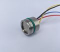
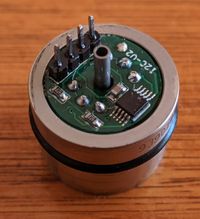
Taking measurements of water pressure can be used to calculate the depth at which the reading was taken. The sensor compares the pressure of the water to the atmospheric pressure allowing it to output a relative reading of the water pressure. This permits us to take an reasonably accurate measurement of the water depth.
We have two similar depth sensors that output either an analog or i2c signal both of which can be received by most micro-controller devices.
19th March 2020
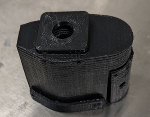
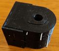
To allow for calibration and testing of the depth sensor, a 3D-printed housing was required. We also incorporated a EC mount into the design. The design had to be waterproof around the depth sensor, the EC prongs and the cable, each requiring o-rings to prevent water passage. It also had to have the depth sensor and EC prongs as close to the bottom of the probe as possible to provide reliable readings at a minimal depth of water. Multiple iterations had to be printed to ensure the tolerances of the 3D printer were accounted for.
22nd March 2020
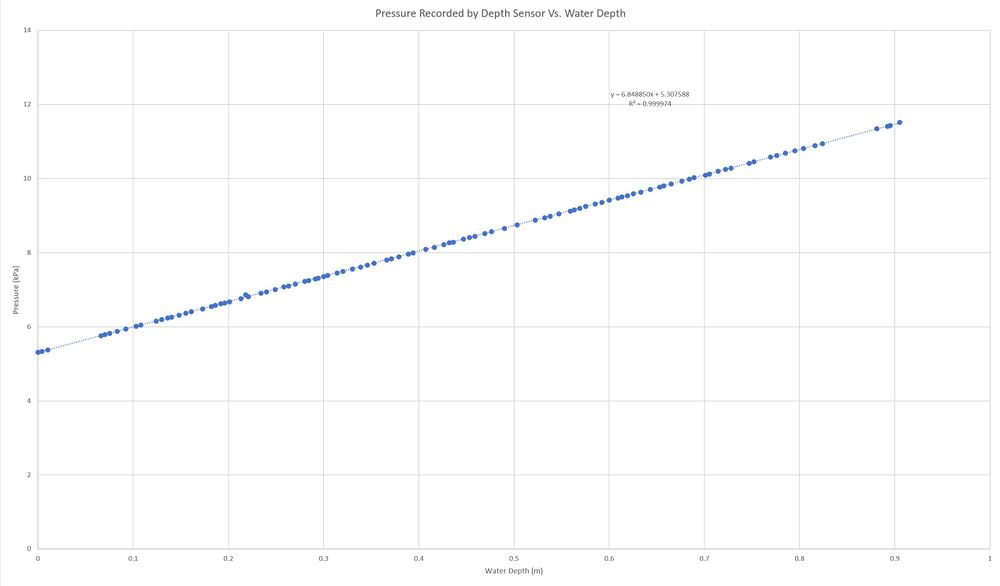
A calibration curve was created for the depth sensor in order to provide an accurate measurement of the water pressure and depth.
Recorded at 3.3 V and 18.90 C, the distance measurements were taken from the face of the sensing element that was 7mm from the bottom of a 19mm diameter tube. From this data we can conclude that the current formula f(x) should be modified to g(x) = 1.4324*f(x)-7.6024 to get an accurate readout of the pressure and h(x) = g(x)/9.81 to get the depth of the water from the sensing element.
If the sensor was exposed to just air on the sensing element, the output of the device was 5.30kPa, which is 15.14% of the maximum output of 35kPa and almost identical to the manufacturers specifications which were 15% of the maximum value.
30th March 2020
An experiment was undertaken to test the stability of the depth sensor. The results acquired were as follows:
| Time (Hours) | Water Depth (m) | Pressure (kPa) | Temperature (C) |
|---|---|---|---|
| 0.00 | 0.904 | 8.87 | 18.9 |
| 50.55 | 0.904 | 8.88 | 17.0 |
| 74.61 | 0.904 | 8.88 | 17.0 |
| 121.98 | 0.904 | 8.87 | 22.7 |
| 146.81 | 0.904 | 8.88 | 22.7 |
| 169.57 | 0.904 | 8.88 | 22.7 |
The fluctuations in the results may be due to slight variations in the water level due to small volumes of the water evaporating and being replaced to maintain a constant water level. The temperature of the water may have also have affected the results.
13th April 2020
Further experimentation was carried out to check the precision and accuracy of the pressure sensor. The results were as follows
| Time (Hours) | Water Depth (m) | Pressure (kPa) | Temperature (C) |
|---|---|---|---|
| 0.00 | 0.905 | 8.8836 | 21.0097 |
| 23.59 | 0.905 | 8.8818 | 21.4496 |
| 47.11 | 0.905 | 8.8885 | 21.1009 |
| 71.61 | 0.905 | 8.8873 | 20.9945 |
| 95.05 | 0.905 | 8.8822 | 20.9065 |
| 118.64 | 0.905 | 8.8870 | 20.3276 |
| 142.24 | 0.905 | 8.8812 | 19.9485 |
| 163.85 | 0.905 | 8.8842 | 20.3499 |
| 191.00 | 0.905 | 8.8846 | 20.4340 |
| 216.71 | 0.905 | 8.8853 | 20.7310 |
| 240.00 | 0.905 | 8.8859 | 20.8577 |
| 263.64 | 0.905 | 8.8883 | 20.1381 |
| 287.93 | 0.905 | 8.8852 | 20.2627 |
The slight variation was most likely due to slight changes in the water depth within a millimeter. Therefore, the pressure is accurate within ±5Pa or ±0.510mm. The experimentation will continue, with the new depth sensors.
The current iteration of the depth sensor housing is waterproof under low water pressures, however, it does start leaking when the water pressure increases.
Using an O-Ring in between the main housing and the top cover greatly increased how waterproof the design was.
To make the design more waterproof, the O-Rings must be forced into the a smaller area. This will be done by further reducing or eliminating space allowed for the O-Rings down to a pinch point where the O-Rings will (hopefully) completely seal the housing!
A PCB was also designed to hold an ATmega328p-au to convert the signals received from the depth sensor and EC into a single data stream and a LN2985 3.3V regulator.
The pins for programming are currently through hole pins, however in future they may be changed to pads to allow more room for proper placement of the depth sensor and cable pins. This design will only work, given that all pins (excluding the EC pins) are flexible. The ECS pin is just in case of another analog input being required. The external crystal was taken out of the circuit and the internal 8MHz clock will be used instead, this should not have a great effect of the performance of the device as speed is not essential. When the exact layout of the pins is known for the depth sensor, a second version will be created that will have the depth sensor and cable pins centralized around the hole in the board (for the back of the depth sensor) and have surface mount pads for the programming pins instead of through-hole mounts to occupy less space of the board.
27th April 2020
PCB v2!
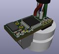
This updated design has all of the pins accurately placed for the new i2c sensor (right) and has through-hole sockets for the EC pins to ensure a secure connection.
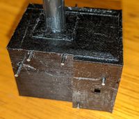
An updated version of the probe housing has also been created, and is waterproof within the testable range of the resources immediately at my disposal. Observe the small holes on the bottom of the housing (Image 3) to allow water in, but prevent damage to the sensor face.
25th June 2020
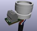
PCB v3! General modifications have been made, including making the board smaller, removal of the prior cable pins and the voltage regulator, changing the downward facing EC prongs to screw terminals and the relocation and reorientation of many components.
The accuracy of the depth sensor has been checked again and records the 0.904m water level as 0.895m, a difference of only 0.9mm over 2 months. The temperature was recorded at 19.48 celsius, whereas the actual temperature was approximately 12-14 celsius. The temperature will need to be calibrated for more accurate measurements.
29th June 2020
A few minor updates to the PCB including the addition of a resistor for the EC and a properly sized screw terminal.
3rd July 2020
A few more minor updates to the PCB, including repositioning the screw terminal to the back of the board and repositioning some components.
10th July 2020
A couple more update to the PCB - added an external crystal, capacitors, and other general modifications.
19th August 2020
A number of updates have been made to the depth sensor.
The PCB for the depth sensor has been manufactured. It currently functions the same as previous versions, however it now has an intermediate stage with an on-board arduino chip interpreting the measurements from the sensors and relaying them onto the second arduino via a serial connection. This allows the depth sensor to be completely controlled at a distance.
Another PCB design for the depth sensor is also being manufactured with a RS-485 communication chip on the PCB. Communicating via a RS-485 module allows multiple sensors to be connected in parallel to a master arduino at significantly longer distances than is possible over a serial connection.
Long term testing for the depth sensors has also been performed. Measurements were taken at a water depth of 450mm (~4.587kPa), however over the testing period the water depth has been observed that the water depth did change within 1mm of the original depth due to variations in the temperature. An observation of note is that the pressure reading are a bit low, this was similarly observed in the continuous testing, and a test will be performed to re-calibrate the readings.
| Time (Hours) | Pressure (kPa) | Experimental Temp. (C) | Approximate Temp. (C) |
|---|---|---|---|
| 0.00 | 4.4570 | 20.0899 | 12 |
| 24.30 | 4.4556 | 19.9766 | 11 |
| 48.42 | 4.4524 | 20.4629 | 14 |
| 72.82 | 4.4505 | 20.7196 | 15 |
| 96.72 | 4.4497 | 20.7266 | 15 |
| 122.57 | 4.4502 | 20.5153 | 14 |
| 145.00 | 4.4488 | 20.7175 | 15 |
| 167.45 | 4.4466 | 20.9399 | 16 |
| 191.37 | 4.4461 | 20.8673 | 16 |
| 215.67 | 4.4528 | 19.9372 | 10 |
| 240.68 | 4.4500 | 19.9881 | 11 |
Continuous testing of the sensors has also been carried out. These measurements were taken in 36 second intervals (was meant to be 360 seconds, error on my part) and recorded the pressure and temperature of the sensor. It can be observed that there is a relationship between temperature and pressure, generally, as the temperature increases, the recorded pressure decreases, this is most likely due to the equilibrium relationship between air and water. Another observation to note is that the readings are lower than expected by approximately 0.012kPa, and will be factored into further testing.
Moving forward, long term testing will continue to ensure stability of measurements over time.
11th September 2020
Further continuous testing has been conducted. The measurement were very precise with errors being approximated at ±2 Pa (±0.2 mm) for the depth component and ±0.005°C. This demonstrates an incredible level of reliability of the short term readings of the sensor. It can also be observed that the "Pressure against time" and "Temperature against time" graphs have an identical shape. Thus, showing the proportional relationship between these two variables. Extrapolating the data shows that at a water depth of 0.600 m and using the density of water as 997.0474 kg/m3 and gravity as 9.80665 m/s2 we can say that the pressure should be 5.87 kPa, whereas the current readout is 5.91 kPa. The temperature that this reading is returned at can be modified, however, 25°C will be chosen as the temperature to have this reading. Scaling this data will have a minor effect on the proportionality constant between pressure and temperature. In the future the density of the water changing could be used to decrease this variability with temperature.
18th October 2020
Further long term testing has been performed. The water depth was initially recorded at 600 mm and over the span of six days the water level dropped by ~2 mm. The data obtained initially indicated a water depth of 599 mm and fell to 598 mm by the second day. Unfortunately, data post this two day period started to output very incorrect readings, differing wildly from the actual values, recording readings between 2.8 - 3.4 m, 9 - 55 °C and a voltage drop of 489 mV. Immediate testing was conducted after this discovery, however the results could not be replicated and thus must be either due to a bug in the code or some physical anomaly. As the data affects the readings of the EC (should be 0V), it is most likely that it was due to a loose wire. Similar testing will continue to ensure that this was due to a loose wire, rather than a larger issue.
| Time (Days) | Pressure (kPa) | Experimental Temp. (C) | Voltage (mV) |
|---|---|---|---|
| 0.25 | 5.866 | 21.724 | 0 |
| 0.50 | 5.866 | 21.738 | 0 |
| 0.75 | 5.865 | 21.741 | 0 |
| 1.00 | 5.865 | 21.740 | 0 |
| 1.25 | 5.865 | 21.742 | 0 |
| 1.50 | 5.865 | 21.742 | 0 |
| 1.75 | 5.865 | 21.742 | 0 |
| 2.00 | 5.865 | 21.744 | 488.76 |
| 2.25 | 32.027 | 55.266 | 488.76 |
| 2.50 | 30.710 | 34.509 | 488.76 |
| 2.75 | 30.903 | 15.568 | 488.76 |
| 3.00 | 32.438 | 9.600 | 488.76 |
| 3.25 | 30.859 | 16.865 | 488.76 |
| 3.50 | 28.992 | 33.471 | 488.76 |
| 3.75 | 29.454 | 51.893 | 488.76 |
| 4.00 | 33.665 | 10.638 | 488.76 |
| 4.25 | 33.743 | 52.152 | 488.76 |
| 4.50 | 32.983 | 9.600 | 488.76 |
| 4.75 | 31.723 | 37.882 | 488.76 |
| 5.00 | 31.379 | 10.897 | 488.76 |
| 5.25 | 30.007 | 37.103 | 488.76 |
| 5.50 | 28.651 | 11.676 | 488.76 |
4th November 2020
Further testing with the regular rxtx depth sensor was conducted. Again, after exactly two days (48 hours), the readings went from precise data to wildly sparse. This test was conducted for an extended period of time to see if a pattern in the sparse data could be observed, however this was to no avail. It should also be noted that the temperature readings were too precise to be considered accurate, that is, the temperature did not vary by ±0.02°C over the course of two days. This is almost impossible and consequently, a calibration of this will be carried out in the future. Another interesting observation is that the EC readings changed by a consistent amount between this experiment and the last, that is from 0 to 488.76. This points to there being an error in the programming of the board.
| Time (Hours) | Pressure (kPa) | Experimental Temp. (C) | Voltage (mV) |
|---|---|---|---|
| 6 | 5.847 | 20.873 | 0 |
| 12 | 5.846 | 20.884 | 0 |
| 18 | 5.846 | 20.890 | 0 |
| 24 | 5.846 | 20.893 | 0 |
| 30 | 5.846 | 20.892 | 0 |
| 36 | 5.846 | 20.895 | 0 |
| 42 | 5.847 | 20.892 | 0 |
| 48 | 5.846 | 20.898 | 0 |
| 54 | 27.409 | 13.492 | 488.76 |
Long term in lab test - started on 4th Nov 2020
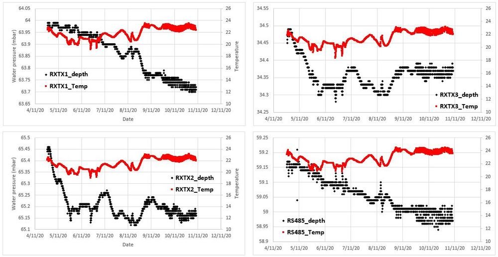
To test our depth sensor V2, we have set up four sensors in out water living laboratory (3 RXTX ones and one RS485 one)
- Luke to take a photo of the lab setup and put it here
- 10th Nov: First week of data
- Pressure was dropping over time --> mainly caused by evaporation
- some minor fluctuation was observed (within 0.05 mbar --> roughly equal to 0.5 mm of water level)
- the impact of water temperature on water depth has not been corrected in the results shown below
- for some of these pressure spikes, we observed a sudden temperature drop or increase as well, which is what has been expected; when calculate water level, the temperature impact can be considered
- all four sensor's temperature measurements picked up the same trend (event with the same fluctuations over time)
- it is important next to test how quick the temperature module can respond to quick changing water temperature
Overall, the depth sensor demonstrated reliable performance in the 1st week of this long term test, without showing any significant sensor drift!
Design
