Difference between revisions of "BoSL Bead Beater"
| (16 intermediate revisions by the same user not shown) | |||
| Line 1: | Line 1: | ||
| + | This section shows the BoSL bead beater. | ||
| + | The BoSL bead beater is a low-cost, open-source, freely available 3d printed bead beater for DNA and RNA extraction. The device can fit with any commercially available portable jigsaw, the 3D-printed components can extract six samples at a time, and the bead beating function is achieved by driving the sample through the rapid movement of the jigsaw blade. | ||
| + | |||
| + | == Latest Design == | ||
| + | |||
| + | [[File:Bead beater version 5.jpg|center|800px]] | ||
| − | |||
| − | |||
== Design Journey == | == Design Journey == | ||
| − | ===''''' | + | ==='''''Version 1'''''=== |
At the start, the initial design key points are <br> | At the start, the initial design key points are <br> | ||
| Line 13: | Line 17: | ||
{| | {| | ||
|- | |- | ||
| − | | [[File:Bead beater design 1.1.png|thumb|Bead beater design 1]] | + | | [[File:Bead beater design 1.1.png|thumb|Bead beater design version 1]] |
| − | | [[File:Bead beater design 1 demo.png|200px|thumb|design 1 demo]] | + | | [[File:Bead beater design 1 demo.png|200px|thumb|design version 1 demo]] |
|} | |} | ||
| Line 21: | Line 25: | ||
For this design, we found that the blade was easily dropped out from the cylindrical clamp component, and the connection parts between the screw base and clamp component were easy to break. Therefore durability of this design was not good. Also, the total length of the design was too long, it causes too much horizontal vibration. | For this design, we found that the blade was easily dropped out from the cylindrical clamp component, and the connection parts between the screw base and clamp component were easy to break. Therefore durability of this design was not good. Also, the total length of the design was too long, it causes too much horizontal vibration. | ||
| − | ===''''' | + | ==='''''Version 2'''''=== |
Some further changes were made that combined the connection parts with the screw base. At the same time, invert the cylindrical portion under the screw case and decrease the overall length by inserting the blade part into the screw top. | Some further changes were made that combined the connection parts with the screw base. At the same time, invert the cylindrical portion under the screw case and decrease the overall length by inserting the blade part into the screw top. | ||
| Line 30: | Line 34: | ||
{| | {| | ||
|- | |- | ||
| − | | [[File:Bead beater design 2..png|thumb|Bead beater design 2]] | + | | [[File:Bead beater design 2..png|thumb|Bead beater design version 2]] |
| − | | [[File:Design 2 demo.png|thumb|200px|Design 2 Demo]] | + | | [[File:Design 2 demo.png|thumb|200px|Design version 2 Demo]] |
|} | |} | ||
| Line 37: | Line 41: | ||
''' Results & Findings''' | ''' Results & Findings''' | ||
| − | Compared with the first design, this was relatively stable | + | Compared with the first design, this was relatively stable. Simultaneously, the side connection parts were too cumbersome, and the overall design was too heavy, which led to horizontal wobble still exists. |
| + | |||
| + | ==='''''Version 3'''''=== | ||
| + | To reduce the weight of the whole design, the screw top is changed to a hollow design and remove the redundant part. | ||
| + | The screw base was also modified by replacing the split design with an insertion design. | ||
| + | |||
| + | [[File:Bead beater Design 3.1.png|thumb|center|Bead beater design version 3.1]] | ||
| + | |||
| + | ''' Results & Findings''' | ||
| + | |||
| + | This design is much simpler and lighter. However, the print material is too soft as compared to the blade, which causes the blade to easily fall off. | ||
| + | |||
| + | [[File:Version 3 result.jpg|thumb|center|Version 3 result.]] | ||
| + | |||
| + | ==='''''Version 3.1'''''=== | ||
| + | The blade was perforated and fastened by two small clips and then inserted into the screw base and secured by M3 screws on the side. | ||
| + | |||
| + | {| | ||
| + | |- | ||
| + | | [[File:Bead beater Design 3.png|thumb|Design version 3]] | ||
| + | | [[File:Design 3 demo.png|thumb|170px|Design version 3 Demo]] | ||
| + | | [[File:Design 3 Demo 2.png|thumb|200px|Screws position]] | ||
| + | |} | ||
| + | |||
| + | ''' Results & Findings''' | ||
| + | |||
| + | The design of connecting the blade and the screw top by screws greatly improves the durability of the device. At the same time, the hollow design for the screw top also greatly reduced the weight of the whole device, well reduced the horizontal wobble during operation. | ||
| + | |||
| + | However, although the horizontal wobble is significantly reduced by reducing the overall weight, the wobble still exists, and the wobble from side to side may lead to blade breakage. | ||
| + | |||
| + | ==='''''Version 4'''''=== | ||
| + | |||
| + | To reduce the horizontal wobbling, two bolts were added at the bottom of the foot base plate to drive the movement of the blade. And the screw base was updated by adding the corresponding hole for the bolts. Hence, the whole components were moving straight without wobbling. | ||
| + | |||
| + | {| | ||
| + | |- | ||
| + | | [[File:Design version 4.png|thumb|left|Bead beater design version 4]] | ||
| + | | [[File:Version 4 demo.png|thumb|Design version 4 Demo]] | ||
| + | | [[File:Final version.png|300px|thumb|center|Final Version]] | ||
| + | |} | ||
| + | ''' Results & Findings''' | ||
| + | |||
| + | For this verison, the connection part of blade insertion was very weak, it was easy to break after a long period of rapid impact. Therefore, the new design remove the the blade connection part and insert the blade directly into the screw base. | ||
| + | [[File:Version 4 result.jpg|thumb|center|Version 4 result]] | ||
| + | |||
| + | ==='''''Version 5'''''=== | ||
| + | In this design, the blade will insert into the screw base, so the entire screw base will be printed as one piece. Therefore, the strength of the print will be higher compared to a separate design. | ||
| + | |||
| + | {| | ||
| + | |- | ||
| + | | [[File:Bead beater Design 5.png|thumb|center|Bead beater design version 5]] | ||
| + | | [[File:Bead beater Design 5.1.png|thumb]] | ||
| + | |} | ||
| + | |||
| + | ''' Results & Findings''' | ||
| + | |||
| + | During the durability test, it was found that the connection part was still very easy to break. Therefore, it is necessary to increase the thickness of the shell in the connection parts to ensure a strong connection. | ||
| + | |||
| + | ==='''''Version 6'''''=== | ||
| + | |||
| + | This version increases the shell thickness of the screw base where it connects with the jigsaw blade from 8mm to 18mm. This change greatly improves the strength of the screw base but also increases its weight accordingly. | ||
| + | |||
| + | {| | ||
| + | |- | ||
| + | | [[File:Bead beater Design 6.png|thumb|bead beater version 6]] | ||
| + | | [[File:Bead beater Design 6.1.png|thumb|]] | ||
| + | |} | ||
| + | |||
| + | ==='''''Protective Shroud'''''=== | ||
| + | |||
| + | Due to the safety hazards during the operation of the jigsaw, there is a high risk of accidents such as cuts and injuries. Moreover, the PLA printing material is relatively fragile and easily damaged. Hence, a protective shroud was designed for this reason. | ||
| + | |||
| + | The protective shroud has the rectangular base plate attached to the jigsaw’s foot base plate by the four M4 screws. And a protective grid box with a lid was connected at the base plate to cover the blade and screw component. | ||
| + | |||
| + | It can protect the blade and prevent the sample tubes spilled outside the screw base. This ensures the operator's safety and prevents the sample from falling off during shaking. | ||
| + | Also, two M6 bolts were installed at the protective shroud's base plate to ensure the whole component's vertical movement. | ||
| + | |||
| + | |||
| + | [[File:Protective shroud.png|thumb|center|Protective shroud]] | ||
| + | |||
| + | |||
| + | == Durability Test == | ||
| + | The purpose of the durability test is evaluating the proformance and longevity of 3D printed components. These tests simulate real-world conditions to determine how well a printed can withstand wear and environmental factors over time. | ||
| + | ==='''''Setting '''''=== | ||
| + | Frequency:45 seconds or 1 minutes | ||
| + | break interval: 5-10 seconds | ||
| + | Checking Components :every 3 mins | ||
| + | |||
| + | ==='''''Version 4 (29/11/2022) '''''=== | ||
| + | At the start of the design, the screw used to fasten the blade was normal M3 zinc screw. However, those screw was cutted by blade during the testing after half an hour testing. | ||
| + | Therefore, the stainless steel screws were used to increase the running time. | ||
| + | |||
| + | ==='''''Version 4 (10/03/2023) '''''=== | ||
| + | The design connection parts failed after one hour of continuous operation. | ||
| − | ===''''' | + | ==='''''Version 5 (13/03/2023) '''''=== |
| + | This design was tested twice, and the connection part still broke. The average time of fracture was 85 minutes. | ||
Latest revision as of 01:48, 26 April 2023
This section shows the BoSL bead beater. The BoSL bead beater is a low-cost, open-source, freely available 3d printed bead beater for DNA and RNA extraction. The device can fit with any commercially available portable jigsaw, the 3D-printed components can extract six samples at a time, and the bead beating function is achieved by driving the sample through the rapid movement of the jigsaw blade.
Contents
Latest Design
Design Journey
Version 1
At the start, the initial design key points are
- Using a screw base and top to hold the extraction sample.
- Connection parts to connect the jigsaw blade and screw base.
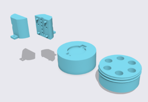
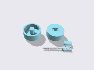
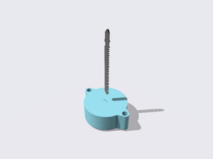
Firstly, we made a circular screw base and top with a 64mm diameter and 6 sample placement holes. Meanwhile, a two-piece cylindrical clamp component clutched the jigsaw blade with studs and M4 screws. Then that cylindrical component is connected to the screw base by using two M4 screws.
Results & Findings
For this design, we found that the blade was easily dropped out from the cylindrical clamp component, and the connection parts between the screw base and clamp component were easy to break. Therefore durability of this design was not good. Also, the total length of the design was too long, it causes too much horizontal vibration.
Version 2
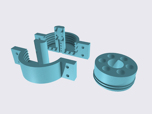
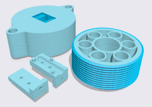
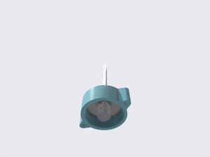
Some further changes were made that combined the connection parts with the screw base. At the same time, invert the cylindrical portion under the screw case and decrease the overall length by inserting the blade part into the screw top. The screw base is divided into two parts with the addition of "studs" on the connecting surface in the middle. These two pieces can be combined with "studs" and used to fasten the jigsaw blade with M4 screws.
Also, a hole was carved in the middle of the screw top to ensure that the extension part of the screw base could be passed and screwed perfectly.
Results & Findings
Compared with the first design, this was relatively stable. Simultaneously, the side connection parts were too cumbersome, and the overall design was too heavy, which led to horizontal wobble still exists.
Version 3
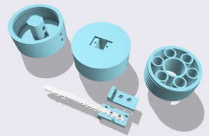
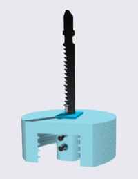
To reduce the weight of the whole design, the screw top is changed to a hollow design and remove the redundant part. The screw base was also modified by replacing the split design with an insertion design.
Results & Findings
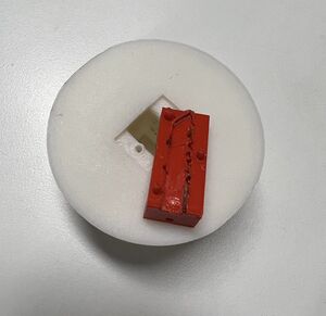
This design is much simpler and lighter. However, the print material is too soft as compared to the blade, which causes the blade to easily fall off.
Version 3.1
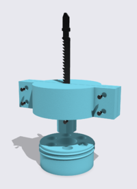
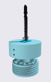
The blade was perforated and fastened by two small clips and then inserted into the screw base and secured by M3 screws on the side.
Results & Findings
The design of connecting the blade and the screw top by screws greatly improves the durability of the device. At the same time, the hollow design for the screw top also greatly reduced the weight of the whole device, well reduced the horizontal wobble during operation.
However, although the horizontal wobble is significantly reduced by reducing the overall weight, the wobble still exists, and the wobble from side to side may lead to blade breakage.
Version 4
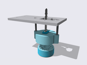
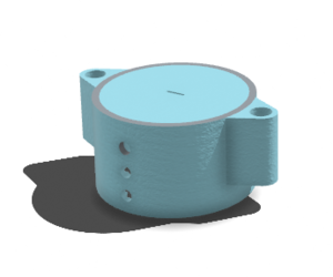
To reduce the horizontal wobbling, two bolts were added at the bottom of the foot base plate to drive the movement of the blade. And the screw base was updated by adding the corresponding hole for the bolts. Hence, the whole components were moving straight without wobbling.
Results & Findings
For this verison, the connection part of blade insertion was very weak, it was easy to break after a long period of rapid impact. Therefore, the new design remove the the blade connection part and insert the blade directly into the screw base.
Version 5
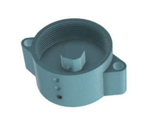
In this design, the blade will insert into the screw base, so the entire screw base will be printed as one piece. Therefore, the strength of the print will be higher compared to a separate design.
Results & Findings
During the durability test, it was found that the connection part was still very easy to break. Therefore, it is necessary to increase the thickness of the shell in the connection parts to ensure a strong connection.
Version 6
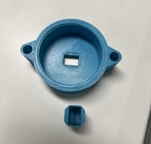
This version increases the shell thickness of the screw base where it connects with the jigsaw blade from 8mm to 18mm. This change greatly improves the strength of the screw base but also increases its weight accordingly.
Protective Shroud
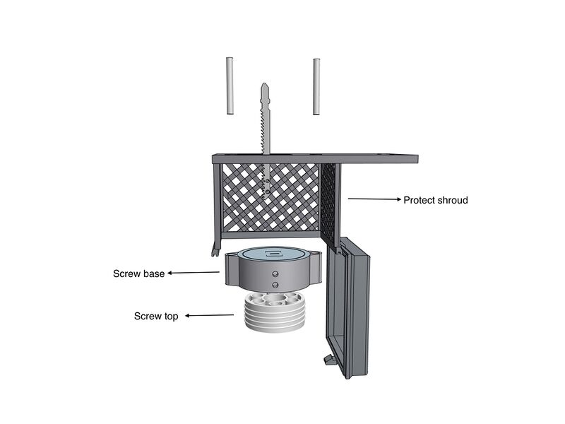
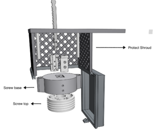
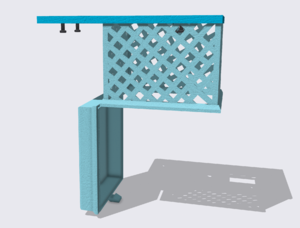
Due to the safety hazards during the operation of the jigsaw, there is a high risk of accidents such as cuts and injuries. Moreover, the PLA printing material is relatively fragile and easily damaged. Hence, a protective shroud was designed for this reason.
The protective shroud has the rectangular base plate attached to the jigsaw’s foot base plate by the four M4 screws. And a protective grid box with a lid was connected at the base plate to cover the blade and screw component.
It can protect the blade and prevent the sample tubes spilled outside the screw base. This ensures the operator's safety and prevents the sample from falling off during shaking. Also, two M6 bolts were installed at the protective shroud's base plate to ensure the whole component's vertical movement.
Durability Test
The purpose of the durability test is evaluating the proformance and longevity of 3D printed components. These tests simulate real-world conditions to determine how well a printed can withstand wear and environmental factors over time.
Setting
Frequency:45 seconds or 1 minutes break interval: 5-10 seconds Checking Components :every 3 mins
Version 4 (29/11/2022)
At the start of the design, the screw used to fasten the blade was normal M3 zinc screw. However, those screw was cutted by blade during the testing after half an hour testing. Therefore, the stainless steel screws were used to increase the running time.
Version 4 (10/03/2023)
The design connection parts failed after one hour of continuous operation.
Version 5 (13/03/2023)
This design was tested twice, and the connection part still broke. The average time of fracture was 85 minutes.
