Difference between revisions of "BoSL mouting system"
| (One intermediate revision by the same user not shown) | |||
| Line 48: | Line 48: | ||
== 6th March 2022 == | == 6th March 2022 == | ||
| − | It was decided that in order to reduce the rotation issue two shower curtain rails will be used. This leads to the following holders for sensors, and for the BoSL board | + | It was decided that in order to reduce the rotation issue two shower curtain rails will be used. This leads to the following holders for sensors, and for the BoSL board box. |
<gallery> | <gallery> | ||
| Line 54: | Line 54: | ||
File:Box mounting two pipe.png | File:Box mounting two pipe.png | ||
</gallery> | </gallery> | ||
| + | |||
| + | The sensor mount can be downloaded here: [https://github.com/Monash-BoSL/mounting-system] | ||
| + | |||
| + | == 13th March 2022 == | ||
| + | |||
| + | A small change was made to the mount for the BoSL board box. Instead of the screw clips attaching from the to the underside of the mount (where they might fall off if too great a force is applied) they will be attached to the other side, where they will have a surface to rest on. | ||
Latest revision as of 11:33, 21 March 2022
This page is dedicated to the BoSL sensor mounting System.
The BoSL sensor mounting system is used to have a universal interface from BoSL sensors for installation. It is designed to provide a secure and robust attachment of the sensor, while also being easy to remove and replace in the field.
Contents
Summary
The interface between the sensor and mount is a ball and socket joint. A threaded collet can be screwed over the ball and socket joint to lock it into position. This ball and socket joint can be 3D printed from the files below. Specifically the ball to be placed on the sensor is 15 mm in radius or 30 mm in diameter. An R-22 o-ring should be place in the collet to improve the gripping strength. Lubricant grease can also be placed between the socket and the collet (not on the ball) to allow the collet to be tightened easier.
A note on printing: to print the nut on the thread, the male and female threads should have a clearance of 0.4 mm. Additionally, printing the nut 1 3d printed layer above a plastic surface will allow it to be freed with a fait bit of force after printing.
Design
7th December 2021
Some work was done on a mount for the radar sensor, the first idea was to use a ball and socket joint which could be secured by a set screw. The ball and socket part of the joint worked well with the ball clipping nicely into the socket, however the set screw part did not work as nicely. This was essentially because the spring-ness needed in the side clip to insert the ball into the socket also caused set screw to open up the socket when tightened. Hence not clamping down on the ball very hard. The next idea was to use a collet.
The rev 0.1.1 radar pcb's were also verified to be working. Some improvements were made to the radar firmware to decrease the measurement time. 4 seconds were saved, which represents about a 30% decrease for the 6 measurement average and 80% for the single measurement. The changes to include more detailed depth measurements were also propagated into the code and verified.
Here is the collet. This worked better than the set screw however still needs a bit of tweaking to get the locking very tight
9th December 2021
The the tolerances on the collet were fixed and now it worked very nicely for locking the sensor. The key change was adding a slot for an o-ring to clip into, this added the necessary extra grip to lock the sensor in place.
10th December 2021
Some further changes were made the the collet to increase the part width where it was a bit small which increases durability. A metric R22 O-ring is used in the design. It is helpful to put some lubricant on the thread and between the collet and chuck (not the ball socket!) as this keeps the collet from binding while being tightened. This is not essential however and is mostly useful for multiple tightening's and loosening's.
15th December 2021
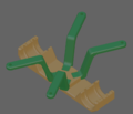
Below is a picture of the clasping mechanism used to support the sensor off a single rail. The screw in the centre is tightened and loosened to adjust the mechanism. One issue noted was that even with very high clamping forces the sensor could still rotate. This is because the support rail does not have a locked rotation and rotating and thus, turning the sensor also turns the support rail. A two support rail mechanism will also be investigated, a goal of this version is also to eliminate all screws in the design.
6th March 2022
It was decided that in order to reduce the rotation issue two shower curtain rails will be used. This leads to the following holders for sensors, and for the BoSL board box.
The sensor mount can be downloaded here: [1]
13th March 2022
A small change was made to the mount for the BoSL board box. Instead of the screw clips attaching from the to the underside of the mount (where they might fall off if too great a force is applied) they will be attached to the other side, where they will have a surface to rest on.


