Difference between revisions of "BoSL Probe No1"
| (16 intermediate revisions by 4 users not shown) | |||
| Line 1: | Line 1: | ||
| + | == We published our BoSL probe to MDPI Sensors! == | ||
| + | The work we have done surrounding this BoSL low-cost water depth, temperature and EC sensor is now published on MDPI Sensors journal!<br> | ||
| + | Apart from showing you the design files, which you can download and use it on your own, we also discussed the sensor performance and long term durability under the field condition!<br> | ||
| + | Please check the full manuscript here at the open-access [https://doi.org/10.3390/s21093056 MDPI Sensors] journal.<br> | ||
| + | |||
== 11th December 2019 == | == 11th December 2019 == | ||
| Line 4: | Line 9: | ||
[[File:BoSL Probe.png|thumb|BoSL Probe]] | [[File:BoSL Probe.png|thumb|BoSL Probe]] | ||
| + | |||
| + | == 17th December 2019 == | ||
| + | |||
| + | A new probe is on its way, I found that applying some ethanol to a tool helps it to shape the waterproof epoxy and smooth to create a more even surface. | ||
| + | |||
| + | [[File:Probe Drying.png|thumb|BoSL Probe Drying]] | ||
| + | |||
| + | == 18th December 2019 == | ||
| + | |||
| + | The probe was filled with waterproof epoxy and left to cure. It takes about one tube to fill the cavity so it might be beneficial to optimise the shape of the probe so that less epoxy is used. | ||
| + | |||
| + | [[File:Epoxy.png|thumb|Epoxy filled BoSL Probe]] | ||
| + | |||
| + | == 19th December 2019 == | ||
| + | |||
| + | The sensor made yesterday died only after a few hours of in water testing. The epoxy used was PC Clear Clear Liquid Epoxy Multi-Purpose "waterproof" clear epoxy. It appears that it is not very waterproof however. | ||
| + | |||
| + | == 21st January 2020 == | ||
| + | |||
| + | A new casing was made for the all-in-one probe with a top bottom split. This should make assembly easier and help reduce the overall height profile of the sensor. The print was made without supports and was mostly successful in this. Some of the overhangs produced poor results and so changes to the design which supports these better when printing should be made. The metal temperature shroud fits well into the cutout, however the edge of the PCB fits too closely to the casing wall to allow a good seal between the metal shroud and the casing. | ||
| + | |||
| + | Below are some images of the new design. | ||
| + | |||
| + | <gallery> | ||
| + | Bottom Casing with PCB.jpg|Bottom Casing With PCB | ||
| + | Top Casing.jpg|Top Casing | ||
| + | </gallery> | ||
| + | |||
| + | == 14th April 2020 == | ||
| + | I thought it was about time we placed our wiring configuration online. Here is the run down.<br><br> | ||
| + | |||
| + | <b>Our Ethernet port is configured as follows (from left to right, looking at the copper prongs):</b><br> | ||
| + | Orange/White - this is connected to our EC sensor on the BoSL probe - Connected to A0 on the BoSL board<br> | ||
| + | Orange - this powers our depth and temperature sensors on the BoSL probe - Connected to 3.3v on the BoSL board<br> | ||
| + | Green/White - this is not used in our BoSL probe - Connected to A1 on the BoSL board<br> | ||
| + | Blue - this is used to communicate to our depth sensor on the BoSL probe - Connected to SCL on the BoSL board<br> | ||
| + | Blue/White - this connected to our Temperature sensor on the BoSL probe- Connected to A2 on the BoSL board <br> | ||
| + | Green - this is the ground for our BoSL probe - Connected to Ground on the BoSL board<br> | ||
| + | Brown/White - this is connected to our EC sensor on the BoSL probe - Connected to A3 on the BoSL board<br> | ||
| + | Brown - this is used to communicate to our depth sensor on the BoSL probe - Connected to SDA on the BoSL board<br> | ||
| + | |||
| + | <br> | ||
| + | <br> | ||
| + | <b>LONG CABLES - due to the instability in I2C communication, we needed to swap a few things around to make this a bit more stable. So for long cables, please wire as follows (from left to right, looking at the copper prongs):</b><br> | ||
| + | Brown/White - this is connected to our EC sensor on the BoSL probe - Connected to A3 on the BoSL board<br> | ||
| + | Orange - this powers our depth and temperature sensors on the BoSL probe - Connected to 3.3v on the BoSL board<br> | ||
| + | Green/White - this is not used in our BoSL probe - Connected to A1 on the BoSL board<br> | ||
| + | Blue - this is used to communicate to our depth sensor on the BoSL probe - Connected to SCL on the BoSL board<br> | ||
| + | Blue/White - this connected to our Temperature sensor on the BoSL probe- Connected to A2 on the BoSL board <br> | ||
| + | Green - this is the ground for our BoSL probe - Connected to Ground on the BoSL board<br> | ||
| + | Orange/White - this is connected to our EC sensor on the BoSL probe - Connected to A0 on the BoSL board<br> | ||
| + | Brown - this is used to communicate to our depth sensor on the BoSL probe - Connected to SDA on the BoSL board<br> | ||
| + | |||
| + | == 21st August 2020 == | ||
| + | <b>Our new All-in-One BoSL probe now has a technical specification sheet.</b><br> | ||
| + | Please download from here: | ||
| + | [[File:Datasheet BoslProbe 21082020.pdf]] | ||
Latest revision as of 05:55, 6 June 2021
Contents
We published our BoSL probe to MDPI Sensors!
The work we have done surrounding this BoSL low-cost water depth, temperature and EC sensor is now published on MDPI Sensors journal!
Apart from showing you the design files, which you can download and use it on your own, we also discussed the sensor performance and long term durability under the field condition!
Please check the full manuscript here at the open-access MDPI Sensors journal.
11th December 2019
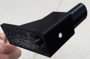
The BoSL Probe enclosure was printed, and is fitting well.
17th December 2019
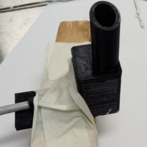
A new probe is on its way, I found that applying some ethanol to a tool helps it to shape the waterproof epoxy and smooth to create a more even surface.
18th December 2019
The probe was filled with waterproof epoxy and left to cure. It takes about one tube to fill the cavity so it might be beneficial to optimise the shape of the probe so that less epoxy is used.
19th December 2019
The sensor made yesterday died only after a few hours of in water testing. The epoxy used was PC Clear Clear Liquid Epoxy Multi-Purpose "waterproof" clear epoxy. It appears that it is not very waterproof however.
21st January 2020
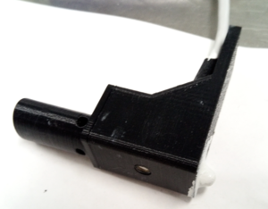
A new casing was made for the all-in-one probe with a top bottom split. This should make assembly easier and help reduce the overall height profile of the sensor. The print was made without supports and was mostly successful in this. Some of the overhangs produced poor results and so changes to the design which supports these better when printing should be made. The metal temperature shroud fits well into the cutout, however the edge of the PCB fits too closely to the casing wall to allow a good seal between the metal shroud and the casing.
Below are some images of the new design.
14th April 2020
I thought it was about time we placed our wiring configuration online. Here is the run down.
Our Ethernet port is configured as follows (from left to right, looking at the copper prongs):
Orange/White - this is connected to our EC sensor on the BoSL probe - Connected to A0 on the BoSL board
Orange - this powers our depth and temperature sensors on the BoSL probe - Connected to 3.3v on the BoSL board
Green/White - this is not used in our BoSL probe - Connected to A1 on the BoSL board
Blue - this is used to communicate to our depth sensor on the BoSL probe - Connected to SCL on the BoSL board
Blue/White - this connected to our Temperature sensor on the BoSL probe- Connected to A2 on the BoSL board
Green - this is the ground for our BoSL probe - Connected to Ground on the BoSL board
Brown/White - this is connected to our EC sensor on the BoSL probe - Connected to A3 on the BoSL board
Brown - this is used to communicate to our depth sensor on the BoSL probe - Connected to SDA on the BoSL board
LONG CABLES - due to the instability in I2C communication, we needed to swap a few things around to make this a bit more stable. So for long cables, please wire as follows (from left to right, looking at the copper prongs):
Brown/White - this is connected to our EC sensor on the BoSL probe - Connected to A3 on the BoSL board
Orange - this powers our depth and temperature sensors on the BoSL probe - Connected to 3.3v on the BoSL board
Green/White - this is not used in our BoSL probe - Connected to A1 on the BoSL board
Blue - this is used to communicate to our depth sensor on the BoSL probe - Connected to SCL on the BoSL board
Blue/White - this connected to our Temperature sensor on the BoSL probe- Connected to A2 on the BoSL board
Green - this is the ground for our BoSL probe - Connected to Ground on the BoSL board
Orange/White - this is connected to our EC sensor on the BoSL probe - Connected to A0 on the BoSL board
Brown - this is used to communicate to our depth sensor on the BoSL probe - Connected to SDA on the BoSL board
21st August 2020
Our new All-in-One BoSL probe now has a technical specification sheet.
Please download from here:
File:Datasheet BoslProbe 21082020.pdf


