Difference between revisions of "In Water Vel Sensor"
| Line 48: | Line 48: | ||
This was accomplished via the following code: | This was accomplished via the following code: | ||
| − | [[File:Fast ADC Code.png | + | [[File:Fast ADC Code.png]] |
Revision as of 01:11, 26 November 2019
This section documented our journey to develop a low-cost water velocity sensor based on doppler effect!
20th November 2019
So the first task we are going to try is to use Arduino to generate 40 kHz square wave and emit that signal by using a ultrasonic transducer.
By facing another same transducer to the one emitting the ultrasonic signal, we can successfully detect that signal.
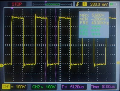
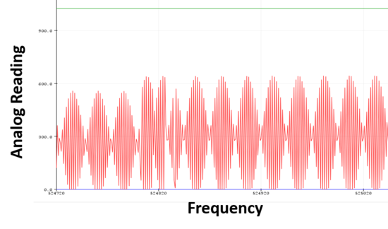
Figures below show the generated square wave from the emitting transducer (measured by an oscilloscope), and the detected wave signal from the receiver transducer (by using AnalogRead).
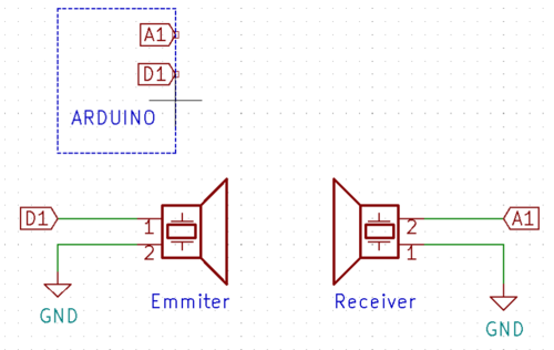
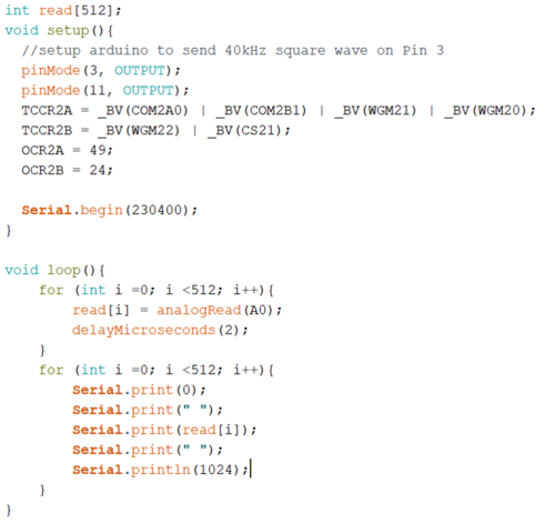
The figure here shows how we wire up the transducers with Arduino to conduct this quick test. The code we used is also attached here to show you how to use Arduino to generate a certain frequency.
21th November 2019
What are we going to try today is to place the two transducers next to each other and facing the same direction.
One emit the signal to a metal wall, and the receiver to detect the signal bounce back.
Multiple op-amps will be used to strength the signal to make it strong enough for Arduino to detect.
25th November 2019
For the arduino to effectively read the low amplitude high frequency signals it is going to need some assistance via external circuitry.
We tested an non-inverting op-amp design based on the LM324. This proved to have challenges reproducing the high frequency signals and after some diagnosis, we determined that the slew rate of the LM324 was too low.
The image above shows the limited slew rate experienced from the LM324N. In this domain the waveform appear as linear as the OpAmp attempts to match the proper signal. It demonstrated a slew rate of about 0.5 V / μS. To overcome this we will need to replace the LM324N with a better OpAmp.
By default the Arduino ADC sample frequency is rather slow at 45 kHz. For our application we will need much faster sampling rates. Fortunately, the clock divider which the ADC runs on (default 32x) is user settable. In testing various values for this, a sample rate of 615 kHz was able to be achieved.


