Difference between revisions of "Turbidity Sensor"
| Line 39: | Line 39: | ||
More to come from Miao in the next few days... | More to come from Miao in the next few days... | ||
| + | |||
| + | <b> 19th November 2019 </b> | ||
| + | |||
| + | This is Miao's turn for updating the process. | ||
| + | |||
| + | Based on Dave's experience, we started to do the calibration of the sensor. | ||
| + | |||
| + | Now we don't want to use a deep cylinder for testing, as the glass cylinder is transparent, we designed a black box and printed it by our 3D printer. The box is designed to fit our sensor and it is 100% infill. | ||
| + | |||
| + | Also, Dave printed another sensor case, which is smaller than the previous one and it has bulgy edges, so it is easier to glue epoxy on the surface of the LED and PT. | ||
| + | |||
| + | [[File:Small testing sensor.jpg|thumb|none]] | ||
| + | |||
| + | So now we have two sensors, the big one which Dave used for testing and a small one with bulgy edges. | ||
| + | |||
| + | After we wired the LED and PT for the small sensor, we tested that, it works and the analog read is more than 400 in air. However, when we cover the epoxy piece on the surface, the reading number became 0 or a quite small number(less than 10). That's weird. We need to wait until the glue drys and then we will test it in water to see if it has any difference. | ||
| + | |||
| + | To be continued…… | ||
| + | |||
<b> 20th Novermber 2019 </b> | <b> 20th Novermber 2019 </b> | ||
| − | + | The glue of the sensors is dry and we put the sensor in water in the black box, the reading number changed to around 920, and when we get it out in the air, the number changed to 12. | |
| − | |||
| − | |||
| − | + | Anyway, as it can be used for testing in water, we started dosing the solution for testing. | |
| + | We use DI water(0.18NTU) and another lab solution(807NTU) to make the solution, we change the testing solution's turbidity by adding more 807NTU solution into DI water and then record the analog reading. | ||
| + | Solution with different turbidity was tested, the range is between 0.18 and 807, from 0.18 to 50 NTU, the step is 5NTU, and the step changes to 10NTU for solution between 50-100NTU, from 100-200NTU, the step is 20 NTU, and from 200-1000NTU solution, the step is 100. Both the big sensor and small sensor are tested. | ||
| − | + | [[File:Testing sensors and boxes|thumb|none]] | |
Revision as of 03:04, 21 November 2019
12th November 2019
So we finally made some nice progress with the Turbidity Sensor design.
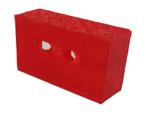
First step was to print our case using our 3D printer. Here it is:
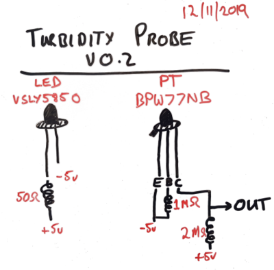
Next step was to test out some hardware for the little guy. We bought two main things: (1) a LED that puts out 850nm wavelength and (2) a phototransistor. The details of the connection we used is here:
We also needed some resistors in the circuit, a 5v power supply and something to read the output (obviously, we used an Arduino)
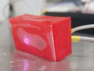
Next step, put it all together and see if it works! So, we used some epoxy and wired this all up to make this sensor:
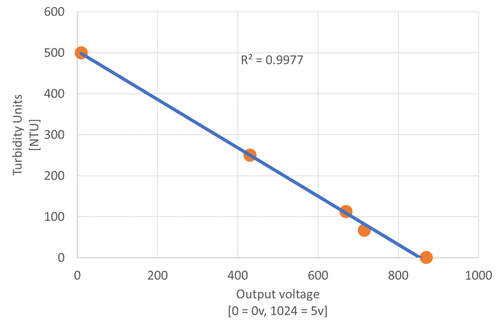
Next step, test the little bugger. We did this using turbidity solutions and a deep cylinder (at least 100mm deep). We tested five turbidity solutions ranging from 500 NTU to 1NTU (tap water). Here are the results we got:
So, in conclusion, we are rather happy with the workings of this cheap turbidity sensor. It costs less than $5 AUD in components, and a little time to put together. The only issue is that the range of the sensor is really limited to just 0 to 500NTU; anything higher and we think we will need to include a photo-diode alongside the phototransistor to get those big NTU values. Also, we are concerned with the energy use that this little puppy dog may take up - the resistors are even heating up (NOT A GOOD SIGN!). The last thing we want to fix is to make this all run on 3.3v instead of 5v...our BoSL board is a 3.3 volt machine, so we want to keep that consistent. Finally (I know, I said the last thing was the final, but this will be) we need to continue to develop our turbidity wiping mechanism...turbidity probes need to be cleaned a lot, so a good wiper is essential or readings are lets just say poor...
Over and out for today.
13th November 2019
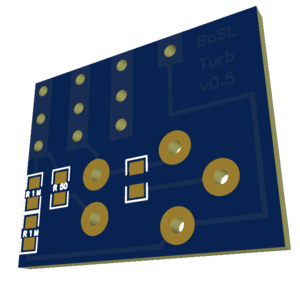
So, today we began making our circuitry for the new turbidity sensor. It is looking good, but when we tried to print the board on our new PCB printer, the ink was all dried up! Come on Voltera, please send us the new ink so we can start printing our boards again! Here is an image of the circuit we made today in an easy to use program called EasyEDA.
17th November 2019
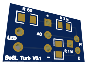
We have begun designing our wiping device, but to do so we needed to revamp our circuit to allow for some motors to drive the wiping action. We began printing many different versions of the above board on our Voltera printer (thanks Voltera for finally giving us our consumables), but there were a hole bunch of issues...including that the holes and pads were not optimised for our Voltera. So, we spent the day designing a new circuit that now looks like...
More to come from Miao in the next few days...
19th November 2019
This is Miao's turn for updating the process.
Based on Dave's experience, we started to do the calibration of the sensor.
Now we don't want to use a deep cylinder for testing, as the glass cylinder is transparent, we designed a black box and printed it by our 3D printer. The box is designed to fit our sensor and it is 100% infill.
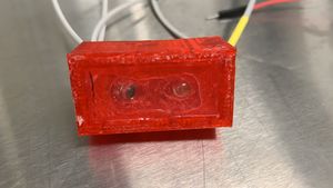
Also, Dave printed another sensor case, which is smaller than the previous one and it has bulgy edges, so it is easier to glue epoxy on the surface of the LED and PT.
So now we have two sensors, the big one which Dave used for testing and a small one with bulgy edges.
After we wired the LED and PT for the small sensor, we tested that, it works and the analog read is more than 400 in air. However, when we cover the epoxy piece on the surface, the reading number became 0 or a quite small number(less than 10). That's weird. We need to wait until the glue drys and then we will test it in water to see if it has any difference.
To be continued……
20th Novermber 2019
The glue of the sensors is dry and we put the sensor in water in the black box, the reading number changed to around 920, and when we get it out in the air, the number changed to 12.
Anyway, as it can be used for testing in water, we started dosing the solution for testing.
We use DI water(0.18NTU) and another lab solution(807NTU) to make the solution, we change the testing solution's turbidity by adding more 807NTU solution into DI water and then record the analog reading.
Solution with different turbidity was tested, the range is between 0.18 and 807, from 0.18 to 50 NTU, the step is 5NTU, and the step changes to 10NTU for solution between 50-100NTU, from 100-200NTU, the step is 20 NTU, and from 200-1000NTU solution, the step is 100. Both the big sensor and small sensor are tested.
